Window regulator device

A technology for car window lifting devices and car window glass, which is applied to windows, vehicle parts, door/window accessories, etc., and can solve the problems of increased manufacturing costs, assembly costs, and deterioration of detection accuracy

Inactive Publication Date: 2012-07-11
AISIN SEIKI KK
View PDF4 Cites 1 Cited by
  • Summary
  • Abstract
  • Description
  • Claims
  • Application Information

AI Technical Summary

Problems solved by technology

When using such a tiny cam member to detect whether the opening and closing position of the window glass is in the dead zone, there is a possibility that the detection accuracy will be greatly deteriorated due to a slight assembly error.
In addition, in order to prevent deterioration of the detection accuracy, when the shape of the cam member and the mounting angle of the pinion are strictly managed, the manufacturing cost and the assembly cost increase.

Method used


Image

  • Window regulator device
  • Window regulator device
  • Window regulator device

Examples


no. 1 Embodiment approach

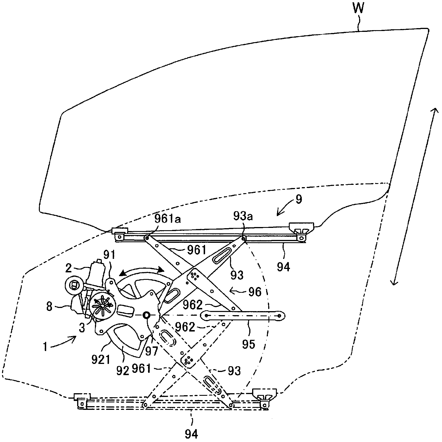
[0061] Hereinafter, a first embodiment of the present invention will be described. figure 1 It is a front view showing the overall structure of the window lifter according to the present embodiment. The window lifter opens and closes a window glass provided on a side window of a vehicle. Such as figure 1 As shown, the window lifter includes a drive mechanism 1 and a drive force transmission mechanism 9 . The drive mechanism 1 includes a motor 2 as a power source for opening and closing a window glass, an output shaft 3 , a case 8 connected to the motor 2 , and a detection unit (not shown) accommodated in the case 8 . The electric motor 2 is electrically connected to a power source such as an on-vehicle battery, and generates rotational driving force by power supply from the power source. The output shaft 3 is rotated by the rotational driving force generated by the motor 2 . The driving force transmission mechanism 9 transmits the rotational driving force of the output s...

no. 2 Embodiment approach

[0150] Next, a second embodiment of the present invention will be described. The structure of the window lifter of the present embodiment is substantially the same as that described in the above-mentioned first embodiment except for the position detection means. Therefore, for the same configuration as that of the first embodiment, description thereof will be omitted with reference to the first embodiment, and a different configuration will be mainly described below.

[0151] The window lifter device according to this embodiment is also used as in the above-mentioned first embodiment. figure 1 As described above, the drive mechanism 1 and the drive force transmission mechanism 9 are provided. Since the structure of the driving force transmission mechanism 9 is substantially the same as that described in the above-mentioned first embodiment, description thereof will be omitted.

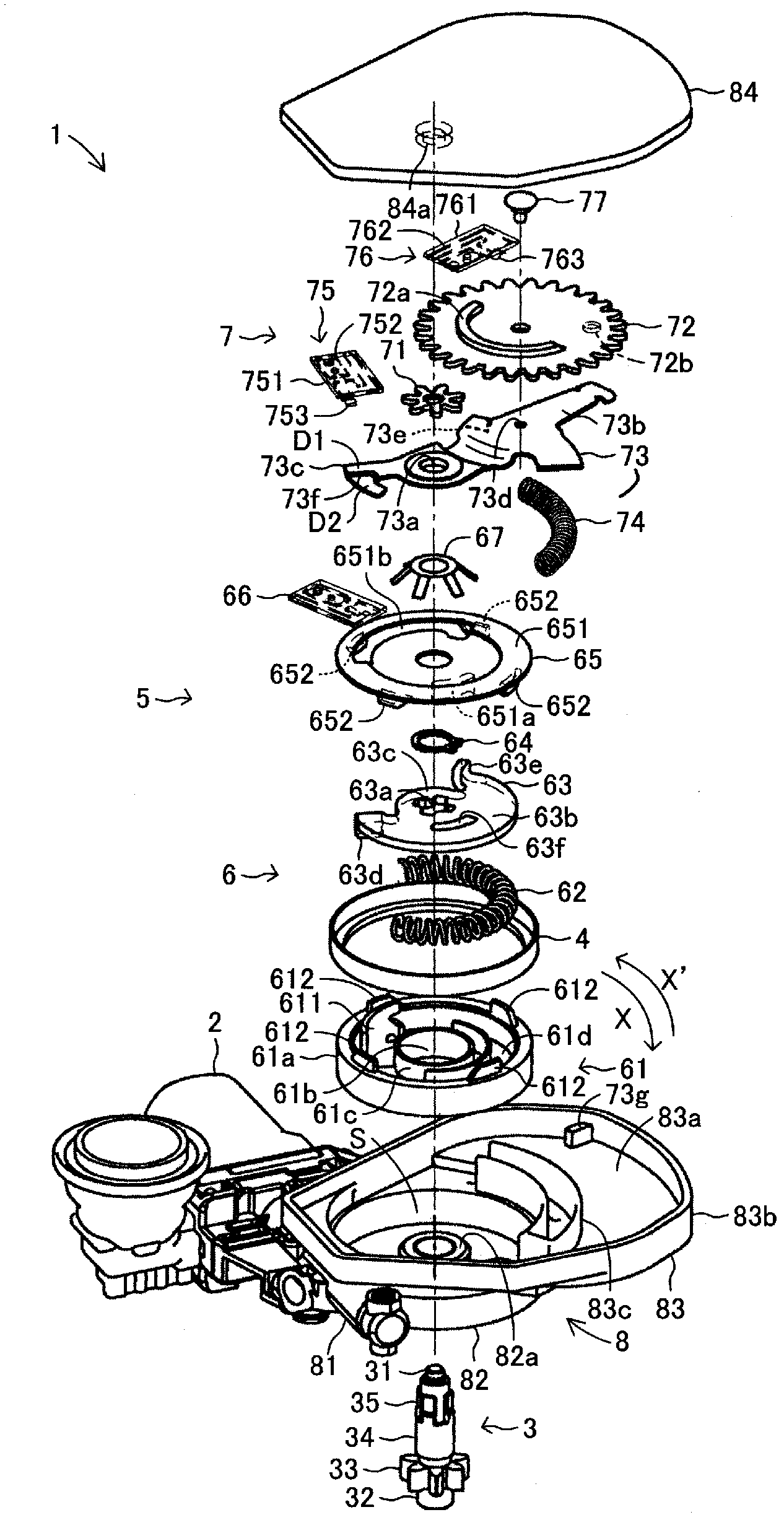
[0152] Figure 28It is an exploded perspective view of the drive mechanism 1 in this embodiment...


PUM


Abstract

A position detection unit is provided with a rotation member which rotates by the rotational driving force of an output shaft; an operation lever which is not engaged with the rotation member when the open or closed position of a window pane is at a location that does not belong to a dead zone region, which is engaged with the rotation member when the open or closed position of the window pane is at a location that belongs to a dead zone region, and which, when thus engaged, performs rotational operation by the rotational driving force of the output shaft, this force being transmitted via the rotation member; and a dead zone region detection switch which performs changeover operation on the basis of the rotational operation of the operation lever. The detection accuracy improves because the dead zone region is detected on the basis of rotational operation of the operation lever.

Description

technical field [0001] The present invention relates to a window lifter for automatically opening and closing a window glass of a vehicle by power generated by a power source such as a motor. In particular, the present invention relates to a window lifter including an opening / closing position detection unit that detects whether the opening / closing position of a window glass falls within a predetermined specific position area. Background technique [0002] The window glass attached to the side window, roof window, etc. of the vehicle has been opened and closed manually in the past, but until now, the window glass of most vehicles has been automatically opened and closed by power generated by a power source such as an electric motor. In the case of automatically closing the window glass, there is a concern that a foreign object may be caught between the window glass and the window frame. At present, a window lift device has been developed that has the following functions. Whe...

Claims


Application Information

Patent Timeline
Patent Type & Authority Applications(China)
IPC IPC(8): E05F15/16B60J1/17E05F15/20
CPCE05Y2400/51E05F11/445E05F15/1684E05Y2900/55E05F15/1692E05F15/20E05Y2400/35E05F15/41E05F15/695E05F15/697E05F15/70
Inventor 片山英史福元良一秋月龙次郎
Owner AISIN SEIKI KK
Why Eureka
Try Eureka