
Switched reluctance motor driving control system, angle control device and method

A switched reluctance motor, angle control technology, applied in control systems, AC motor control, single motor speed/torque control, etc., can solve the problems that the overall efficiency cannot be optimized, the temperature of switching semiconductor components rises, etc., to achieve efficiency optimization , the effect of reducing the opening time

Inactive Publication Date: 2012-07-11
BEIJING CHINA TEX MECHANICAL & ELECTRICAL ENG
View PDF0 Cites 6 Cited by
  • Summary
  • Abstract
  • Description
  • Claims
  • Application Information

AI Technical Summary

Problems solved by technology

[0003] Aiming at the defects in the above-mentioned prior art, the present invention provides a switched reluctance motor drive control system, an angle control device and a method to solve the problem that the switching semiconductor is easily caused when the existing full PWM controller adopts a fixed conduction width The temperature rise of components is too high, and the efficiency cannot be optimized as a whole in the full speed and torque range

Method used


Image

  • Switched reluctance motor driving control system, angle control device and method
  • Switched reluctance motor driving control system, angle control device and method
  • Switched reluctance motor driving control system, angle control device and method

Examples


Embodiment Construction

[0037] figure 2 It is a structural diagram of the drive control system of the switched reluctance motor of the present invention. These include: angle control device;

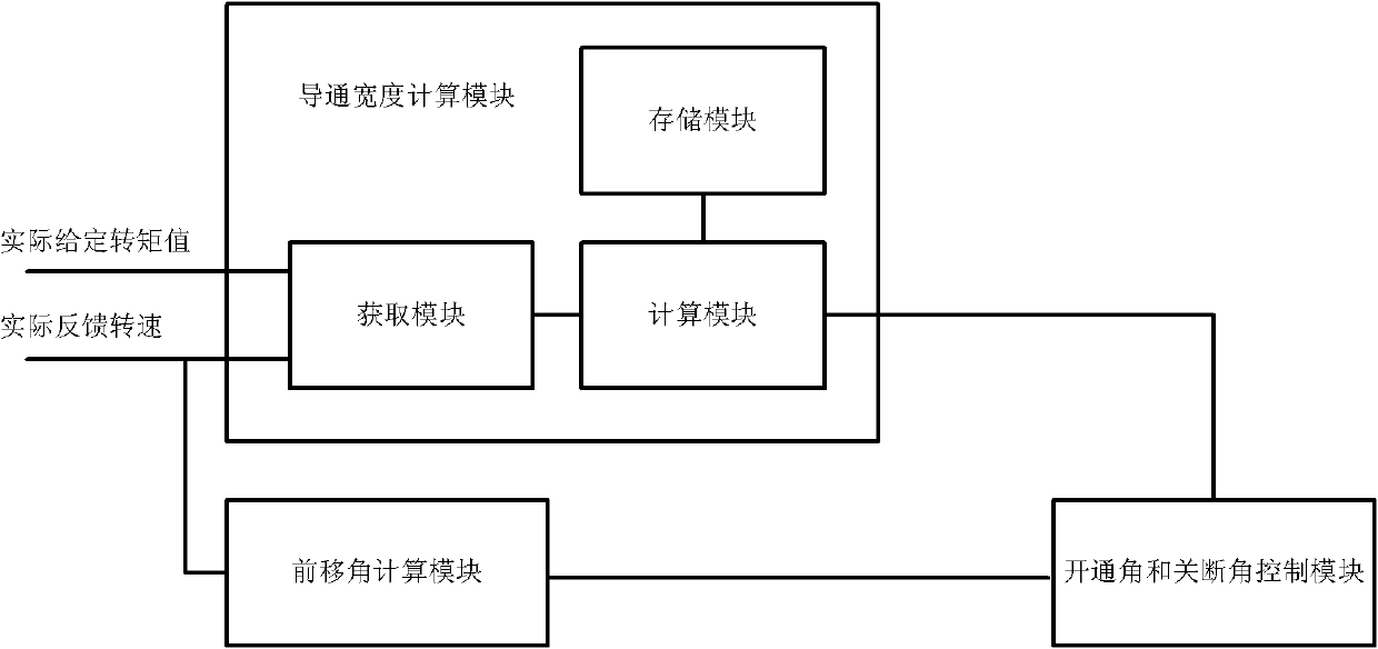
[0038] The angle control device, such as image 3 As shown, it includes: a conduction width calculation module, an advance angle calculation module, and a turn-on angle and turn-off angle control module. The turn-on angle and turn-off angle control modules are used to calculate the conduction width and advance The forward angle calculated by the angle calculation module controls the action of the switching element in the drive control system of the switched reluctance motor to complete the control of the switched reluctance motor. Specifically, according to the conduction width calculated by the conduction width calculation module and the advance angle calculated by the advance angle calculation module, the turn-on angle and turn-off angle control module can obtain the phase conduction interval through progr...


PUM


Abstract

The invention relates to a switched reluctance motor driving control system, an angle control device and a method. The switched reluctance motor angle control method comprises the following steps that: 1, a corresponding relationship table of the given torque value and the conduction width is set in advance under each rotating speed point; 2, the corresponding conduction width under the actual given torque value and the actual feedback rotating speed is calculated through an interpolation algorithm; and 3, the angle control is carried out according to the front displacement angle and the conduction width obtained through the calculation, wherein a turn-off angle is changed along with the rotating speed, during the electric control, the turn-off angle can be obtained by subtracting the front displacement angle from 180 degrees, and a turn-on angle can be obtained by subtracting the conduction width from the turn-off angle; and during the brake control, the turn-off angle can be obtained by subtracting the front displacement angle from 360 degrees, and the turn-on angle can be obtained by subtracting the conduction width from the turn-off angle. The switched reluctance motor driving control system, the angle control device and the method solve the problems that when the fixed conduction width is adopted in the existing full pulse width modulation (PWM) controller, too high temperature rise of switch semiconductor devices can be easily caused, and the efficiency in the full speed and the torque range cannot be integrally optimized.

Description

technical field [0001] The invention belongs to the field of drive control of switched reluctance motors, and relates to a drive control system of switched reluctance motors and an angle control device and method for the drive control system of switched reluctance motors. Background technique [0002] In the drive control of switched reluctance motors, when the existing technology adopts full PWM control, the general fixed conduction width is 180 degrees electrical angle, the conduction angle changes forward with the actual speed of the motor, and the output of the current regulator is the duty cycle of PWM . Such as figure 1 shown. Due to the fixed 180-degree conduction width of this method, the switch semiconductor device has a long turn-on time and a large conduction loss at medium and low speeds or light loads, resulting in high temperature rise and reduced reliability; In the and torque ranges, the conduction width is fixed, resulting in that the efficiency cannot be...

Claims


Application Information

Patent Timeline
IPC IPC(8): H02P6/08H02P25/08
Inventor 高超马良玉蒋哲
Owner BEIJING CHINA TEX MECHANICAL & ELECTRICAL ENG
Learn More