Tripping traction device for circuit breaker

A traction device and circuit breaker technology, which is applied to the operation/release mechanism of the protection switch, etc., can solve the problems such as the inability to arrange the extension traction rod, the large current carried by the circuit breaker, and the long phase-to-phase distance.

Active Publication Date: 2014-02-26
CHANGSHU SWITCHGEAR MFG CO LTD (FORMER CHANGSHU SWITCHGEAR PLANT)
View PDF5 Cites 0 Cited by
  • Summary
  • Abstract
  • Description
  • Claims
  • Application Information

AI Technical Summary

Problems solved by technology

In some applications, such as universal circuit breakers, because the circuit breaker carries a relatively large current (generally rated current is 1600A~7400A), in order to ensure sufficient insulation performance and breaking capacity, the volume of the circuit breaker is relatively large. The distance between the phases is relatively far, and the electromagnets on each phase are relatively far apart, and due to structural limitations, it is impossible to arrange the drawbar extending to the electromagnets of each phase, and the electromagnets of each phase cannot directly hit the drawbar

Method used


Image

  • Tripping traction device for circuit breaker
  • Tripping traction device for circuit breaker
  • Tripping traction device for circuit breaker

Examples


Embodiment Construction

[0018] In order to enable the examiners of the patent office, especially the public, to more clearly understand the technical essence and beneficial effects of the present invention, the applicant will describe in detail the following examples, but none of the descriptions of the examples is a description of the technical solution of the present invention. Any equivalent transformation made according to the concept of the present invention which is merely formal but not substantive shall be regarded as the scope of the technical solution of the present invention.

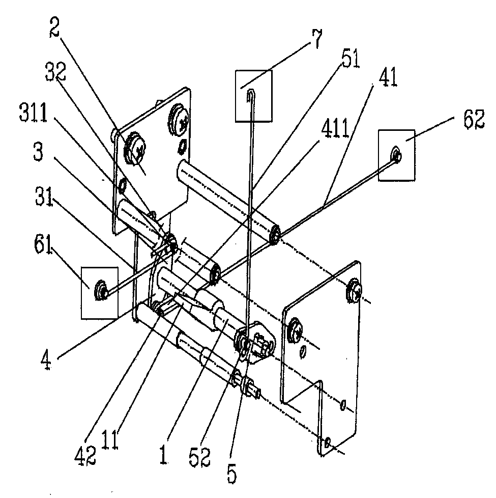
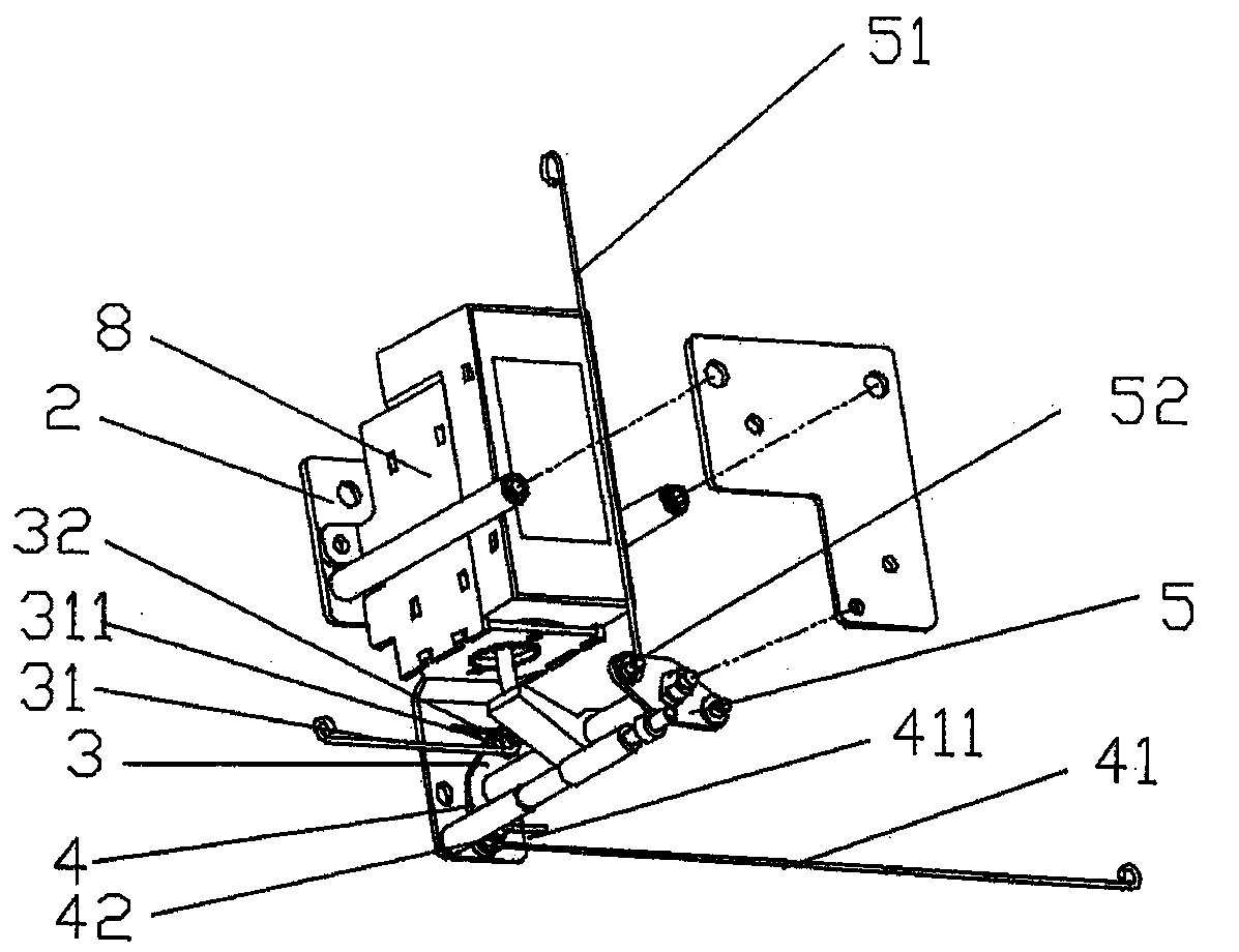
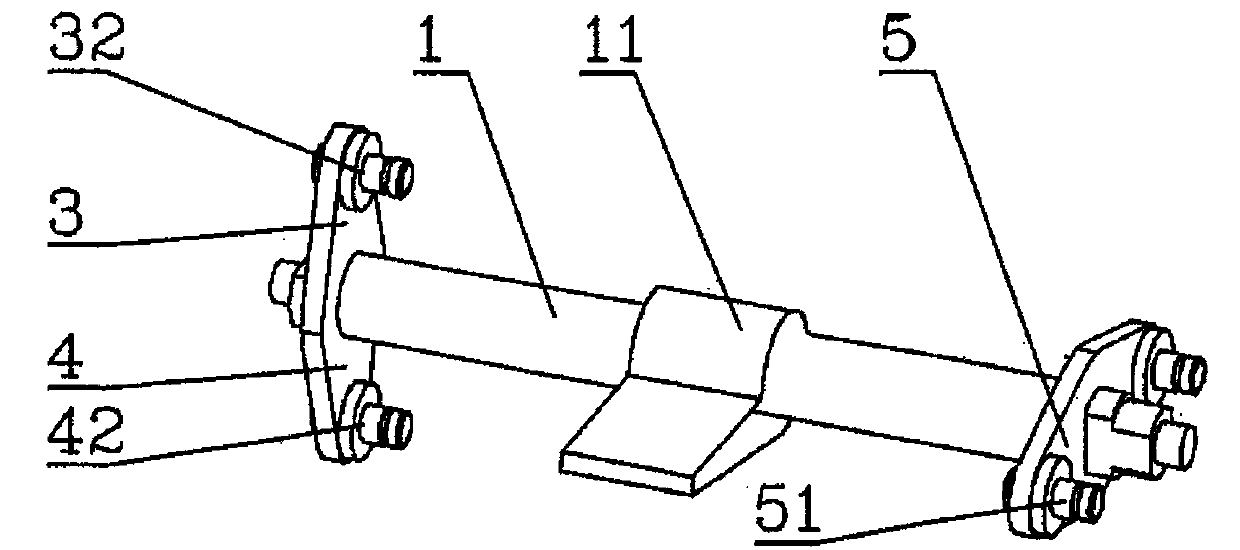
[0019] see figure 1 , figure 2 , image 3 , Figure 4 with Figure 5 , a tripping device for a circuit breaker, the circuit breaker includes a first electromagnet 61, a second electromagnet 62 and an operating mechanism 7 (the structure of the electromagnet is not subject to any restrictions, it can be a snap-on electromagnet, the operation The mechanism is a mechanism that accepts the transmission force of the...


PUM


Abstract

The invention discloses a tripping traction device for a circuit breaker, and belongs to the technical field of low-voltage electrical apparatuses. The circuit breaker comprises a first electric magnet, a second electric magnet and an operating mechanism; the traction device comprises a supporting frame, a traction rod, a first cantilever, a second cantilever, a third cantilever, a first pin shaft, a second pin shaft, a first connecting piece, a second connecting piece and a third connecting piece; the third connecting piece is connected with the operating mechanism; the first electric magnet and the second electric magnet are arranged on two sides of the traction rod respectively; one end of the first connecting piece is connected with the first electric magnet, a first strip-shaped groove is formed at the other end of the first connecting piece, and the first pin shaft is arranged in the first strip-shaped groove to form a sliding fit; and one end of the second connecting piece is connected with the second electric magnet, a second strip-shaped groove is formed at the other end of the second connecting piece, and the second pin shaft is arranged in the second strip-shaped groove to form a sliding fit. The tripping traction device for the circuit breaker has the advantages that: the actuating force of the electric magnets can be effectively transmitted to the operating mechanism, and when one of the electric magnets transmits the force, an adverse effect cannot be caused to the other electric magnet under the condition that the two electric magnets exist.

Description

technical field [0001] The invention belongs to the technical field of low-voltage electrical appliances, and in particular relates to a tripping traction device for a circuit breaker. Background technique [0002] A circuit breaker is a device used in a power supply line system to protect electrical equipment from damage in the event of overload, short circuit and undervoltage protection. In the event of overload, short circuit, etc., the overcurrent protection of the circuit breaker is to output power through electromagnets (such as snap-in electromagnets, solenoid electromagnets, etc.) and actuate the operating mechanism to separate the moving contacts from the static contacts. , to realize the opening of the circuit breaker. Multiple electromagnets are usually installed in a circuit breaker, and multiple electromagnets can actuate the operating mechanism. Therefore, it is necessary to coordinate the actions between multiple electromagnets so that when one electromagnet ...

Claims


Application Information

Patent Timeline
Patent Type & Authority Patents(China)
IPC IPC(8): H01H71/24
Inventor 俞晓峰朱诚周敏琛管瑞良
Owner CHANGSHU SWITCHGEAR MFG CO LTD (FORMER CHANGSHU SWITCHGEAR PLANT)
Why Eureka
Try Eureka