Novel hanger for changing radiant tubes

A radiant tube, a new type of technology, applied in the direction of the lifting device, etc., can solve the problems of poor control of the driving force, poor control, excessive radiant tube, etc., to reduce the risk of excessive insertion and the effect of small size

Inactive Publication Date: 2012-07-11
WISDRI WUHAN WIS IND FURNACE
View PDF10 Cites 5 Cited by
  • Summary
  • Abstract
  • Description
  • Claims
  • Application Information

AI Technical Summary

Problems solved by technology

The simple operation method of the spreader is inconvenient to install, and it is not easy to control the driving force when it is loaded into the furnace. If the driving control is not good, there will be a risk of excessive insertion of the radiant tube into the furnace, especially for high driving in the factory building. When the driving coupler swings, it is even more difficult to control the forward movement of the radiant tube spreader by moving the driving coupler trolley forward.

Method used


Image

  • Novel hanger for changing radiant tubes
  • Novel hanger for changing radiant tubes

Examples


Embodiment Construction

[0014] The present invention will be further described below in conjunction with implementation examples and accompanying drawings, but the present invention is not limited.

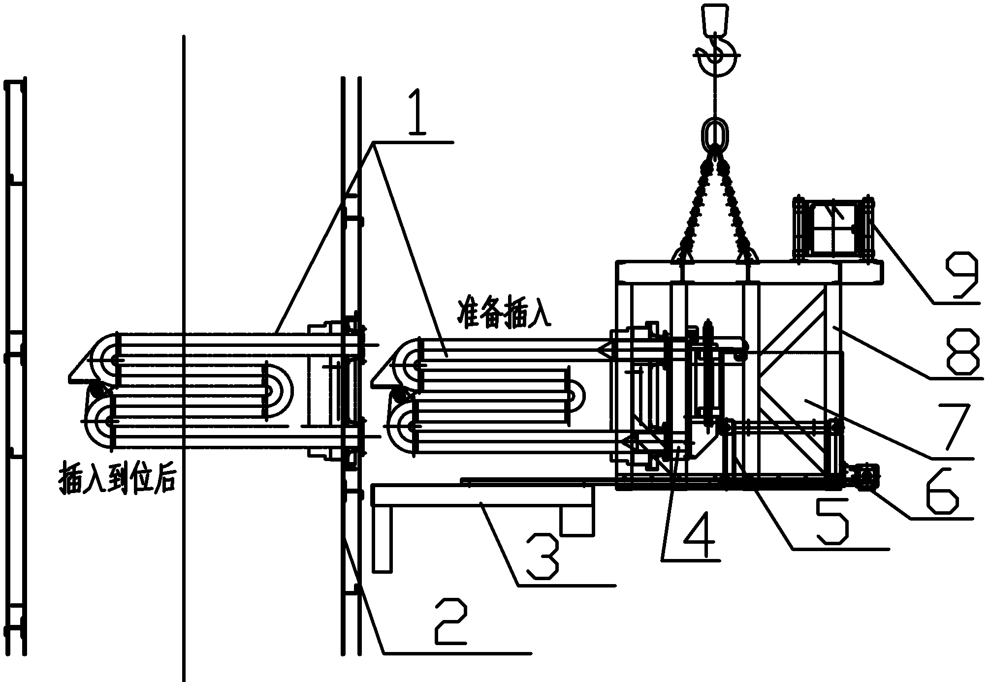
[0015] figure 1 Shown is the novel radiant tube replacement hanger implemented according to the present invention, which is characterized in that it mainly includes a main frame 8 for driving and lifting, and the trolley 5 is arranged on the main frame 8 and can move along the frame 8; the space of the main frame 8 Inner trolley 5 ends are connected with the plunger 4 of fixedly supporting radiant tube, and dolly 5 itself is equipped with configuration box 7, and dolly 5 can drive chain by transmission gear machine 6 on frame 8 to control the advancement and retreat of dolly.

[0016] During operation, the electric control box 9 is controlled by the operation button to realize the advancement of the trolley. After the trolley advances, the radiant tube 1 is fixed, and the trolley 5 is returned to the rac...


PUM


Abstract

The invention relates to a novel hanger for changing radiant tubes, which mainly comprises a main machine frame used for lifting a travelling crane and an inserting rod used for fixing and supporting a radiant tube; upper and lower rods of the inserting rod are respectively inserted in two horizontal tube segments of the radiant tube, the novel hanger for changing the radiant tubes is characterized in that a bogie capable of horizontally moving along the inner space of the main machine frame is arranged on the main machine frame, and the horizontal end head of the bogie is connected with the inserting rod; the inner space of the main machine frame is allocated to enable the bogie and the radiant tube to horizontally move and / or vertically lift together; the bogie is provided with an allocation box; a mounting platform flush with the main machine frame is also arranged on an oven wall where the radiant tube is to be inserted, the main machine frame is arranged on the platform, and the bogie can move forward on the platform. A travelling crane machine frame is separated from the inserting rod, and the inserting rod is controlled by the bogie to move forward sp as to perform a precise tube insertion action, therefore, the excessive insertion risk of the radiant tube caused by the excessive forward movement of the travelling crane is reduced; and the hanger has a small dimension, so that the hanger is suitable for mounting the radiant tubes in factory buildings with small spaces.

Description

technical field [0001] The invention relates to a sling device for installation, replacement and disassembly of a W-shaped radiant tube of a strip steel vertical continuous annealing furnace. Background technique [0002] During the installation, daily maintenance and overhaul of large vertical continuous annealing furnaces for large-scale cold-rolled strip continuous annealing units in various domestic steel mills, especially during the installation stage, due to the large number of radiant tubes in the annealing furnace and the small space for the operating platform, the furnace It cannot be hung, and the installation and maintenance of the radiant tube requires high-altitude operations. In this case, the disassembly and replacement of the radiant tube requires the use of special lifting equipment. [0003] The working principle of the commonly used simple rod-type radiant tube replacement spreader is a frame with a counterweight. Insert a rod into the W-shaped radiant tub...

Claims


Application Information

Patent Timeline
IPC IPC(8): B66F11/00
Inventor 李楠田发禹于海王俊刚
Owner WISDRI WUHAN WIS IND FURNACE
Why Eureka
Try Eureka