Crane girder

A technology for cranes and main girders, applied in the field of cranes, can solve problems such as the easy failure of the supporter, and achieve the effects of good creep resistance, obvious effect, and long maintenance time

Active Publication Date: 2013-12-11
徐清普
View PDF8 Cites 0 Cited by
  • Summary
  • Abstract
  • Description
  • Claims
  • Application Information

AI Technical Summary

Problems solved by technology

[0006] The purpose of the present invention is to provide a crane girder to solve the technical problem that the supporter in the prior art is prone to failure after a period of use

Method used


Image

  • Crane girder
  • Crane girder
  • Crane girder

Examples


Embodiment 1

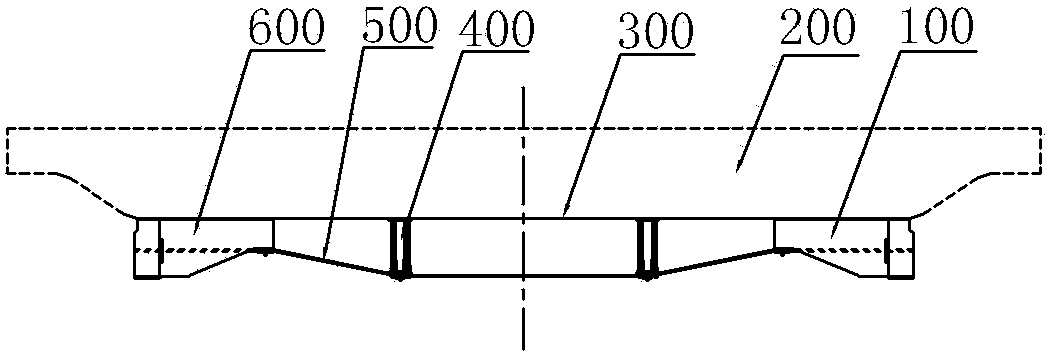
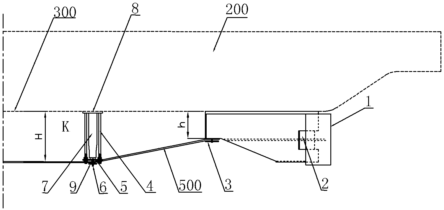
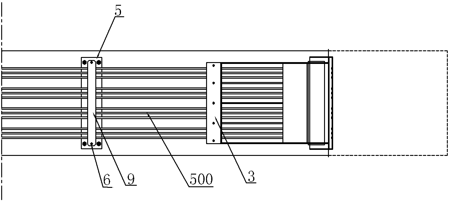
[0031] Such as Figure 1 to Figure 7 As shown, an embodiment of a crane girder, the crane girder 200 in this embodiment includes a lower cover plate 300, and a repair device for repairing the deflection of the main girder is installed on the side of the lower cover plate 300 away from the main girder, The repair device includes a first base 100 and a second base 600 fixed at both ends of the lower cover plate, where the first base 100 is a tension base equipped with tension anchors, and the second base 600 is a fixed The base, between the tension base and the fixed base, can be tensioned and equipped with a plurality of steel strands 500 extending in parallel, one end of the steel strands 500 is fixed in the fixed base, and the other end is in the fixed base. After passing through the tension anchor of the tension base, it is connected with the tension device 11 arranged on the tension base. The tension device 11 here is a hollow hydraulic jack tension device. When in use, the...

Embodiment 2

[0041] The difference between embodiment 2 and embodiment 1 mainly lies in the difference of the middle pushing structure, such as Figure 10 , Figure 11 , Figure 12 As shown, the upper connecting part in the present embodiment is an upper connecting plate 14, the lower connecting part is a round steel 19, and the middle pushing structure is a vertical plate 15, and the lower side of the vertical plate 15 is welded and fixed with the round steel 19, and the upper side is connected with the round steel 19. The upper connecting plate 14 is welded and fixed, and the two ends of the vertical plate 15 along the extension direction of the main beam are respectively welded and fixed with the corresponding supporting studs 18 , and the round steel 19 is fixedly matched with the supporting studs 18 through the vertical plate 15 . Between the round steel 19 and the upper connecting plate 14, two oblique supporting plates 16 are respectively positioned on the left and right sides of t...


PUM


Abstract

The invention discloses a crane girder which comprises a lower cover board, wherein a repair device for repairing down-warping or sidewise bending of the girder is arranged on one side, departing from the girder, of lower cover board; the repair device comprises a first base and a second base which are fixedly arranged at the two ends of the lower cover board; a plurality of tensioning steel strands extending in parallel are assembled between the first base and the second base; at least one of supporting and propping device is arranged between the lower cover board and the steel strands; the supporting and propping device comprises an upper connecting part and a lower connecting part; the upper connecting part is fixedly arranged on the lower cover board during use; the lower connecting part is in propped fit with the steel strands during use; a supporting stud is supported between the upper connecting part and the lower connecting part; the two ends of the supporting stud is in fixed fit with the upper connecting part and the lower connecting part, so that the upper connecting part and the lower connecting part are assembled into a whole; the supporting stud is positioned at two ends of the upper connecting part and the lower connecting part along the girder extending direction; and the supporting and propping device also comprises a middle propping structure which is supported between the upper connecting part and the lower connecting part and used for preventing sidewise bending of the supporting stud. The whole supporting and propping device is stable, so sidewise bending of the supporting stud is effectively avoided.

Description

technical field [0001] The invention belongs to the technical field of cranes, and in particular relates to a main girder of a crane. Background technique [0002] Cranes are widely used in industrial and mining enterprises at home and abroad. According to the requirements of relevant national standards, the camber of the main beam is an important technical index of cranes. GB / T14405-2011 "Universal Bridge Cranes" and GB / T14406-2011 "Universal Gantry Cranes" stipulate that the main girder of the crane needs to be set with a certain camber value. The main purpose is to improve the bearing capacity of the crane and improve the main girder. However, due to the manufacture or use of the crane, such as when the trolley is in the mid-span, and under the rated load, the environment, working conditions and other factors, the main beam appears Camber deflection or side bending deformation is prone to rail gnawing by carts, trolleys "climbing", "rolling", and lower lifting capacity, ...

Claims


Application Information

Patent Timeline
Patent Type & Authority Patents(China)
IPC IPC(8): B66C6/00
Inventor 徐清普
Owner 徐清普
Why Eureka
Try Eureka