Vibration unloading silo with central discharge hopper and unloading method

A technology for discharging hoppers and barrels, which is applied in the field of silos, which can solve the problems that the discharging process requires manual supervision, is easily corroded and damaged, and has high costs, and achieves the effects of avoiding structural defects, fast discharging speed, and reduced cost

Active Publication Date: 2016-04-20
HARBIN BEICANG GRAIN STORAGE PROJECT & EQUIP
View PDF9 Cites 0 Cited by
  • Summary
  • Abstract
  • Description
  • Claims
  • Application Information

AI Technical Summary

Problems solved by technology

However, the warehouse with a flat bottom structure cannot be unloaded by gravity, so only a spiral clearing machine can be used.
This kind of machinery is not only expensive, but it is not only easy to be corroded and damaged when buried under the material when the warehouse is full, but also requires manual supervision during the discharge process, which is very inconvenient

Method used


Image

  • Vibration unloading silo with central discharge hopper and unloading method
  • Vibration unloading silo with central discharge hopper and unloading method
  • Vibration unloading silo with central discharge hopper and unloading method

Examples


Embodiment 1

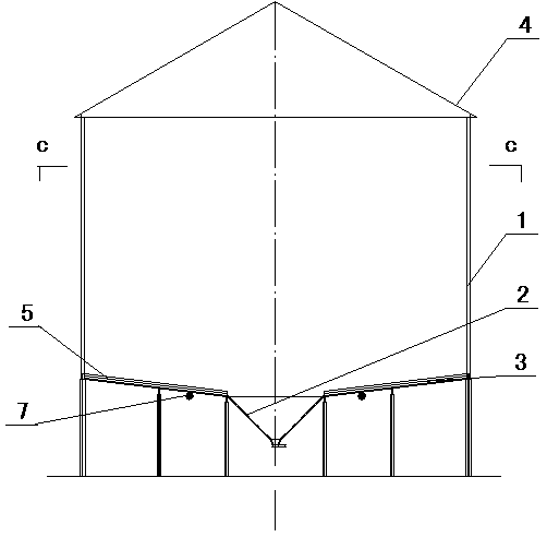
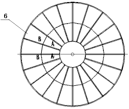
[0031] A vibrating unloading silo with a central hopper, which consists of: a silo body 1, a silo bottom 3 with a central artesian hopper 2 and a silo cover 4, a group of obliquely installed around the central artesian hopper 2 The unloading tray 5, the disc 6 of the unloading tray 5 can be made into a fan-shaped or strip-shaped or polygonal shape, and the described unloading tray is connected with a vibration source 7. The feeding tray is divided into 4-50 pieces according to the diameter of the bin body, mainly divided into fan shapes, which can be divided into several rings first, and then divided along the diameter.

[0032] The vibration source is a vibration motor, or an impact head driven by a pneumatic pump or a hydraulic pump, or an eccentric cam driven by a motor can also be used to generate vibration.

Embodiment 2

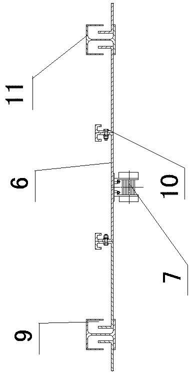
[0034] In the vibrating unloading silo with a central discharge hopper described in Embodiment 1, a return spring 8 is provided at the lower part of the discharge tray, and the return spring can be a leaf spring used on an automobile, or a tension spring or a compression spring , the main function is to raise the disc and separate it from the bottom of the warehouse by a certain distance, which can reduce wear and facilitate vibration work.

Embodiment 3

[0036] For the above-mentioned vibrating discharge silo with a central discharge hopper, the vibration source is a vibration motor or a cam structure connected to the motor, which generates bumpy vibration through the rotation of the cam or vibration through the impact of a pneumatic piston or a hydraulic pulse piston, according to The provision of the vibration source in the environment where the warehouse body is located can also be provided in other ways, and the vibration motor is the best. It has been confirmed through experiments that when the vibration source is installed on the side of the central gravity bucket of the disk , the effect is better, and the material behind will speed up the flow rate and increase the flow rate during the process of slumping and self-flowing. Generally, the vibration source can be installed on the downward side of the disc, which is convenient for maintenance and can avoid moisture erosion.


PUM


Abstract

The invention relates to a vibratory discharge silo with a central discharge hopper and a discharge method. A conical bottom structure mostly adopted by an existing silo in discharge is large in silo height occupancy, low in volume rate and high in center of gravity. The vibratory discharge silo with the central discharge hopper structurally comprises a silo body (1), a silo bottom (3), a silo cover (4) and a group of discharge disks (5), wherein the silo bottom (3) is provided with the central automatic discharge hopper (2), and the discharge disks (5) are centripetally and obliquely mounted around the central automatic discharge hopper (2), comprise sector-shaped, strip-shaped or polygonal disk pieces (6) and are connected with vibration sources (7). The silo can be used for storing materials such as grains, coal and the like.

Description

Technical field: [0001] The invention relates to a silo with a central discharge hopper and a vibration discharge device, and a vibration discharge method for the silo. Background technique [0002] Bulk materials such as grain, minerals, etc. have a large flow rate and require a high degree of mechanization. The material out of the warehouse has always been a worldwide problem. For small silos, such as silos with a diameter of less than 10m, the bottom can be made into a cone, and the material It can completely flow out of the warehouse by itself, meeting the requirements of mechanized production. However, due to the large diameter of the large silo, if the bottom is made into a cone, the space height is very high, and the cost is also very high. Take the granary as an example. At present, the common practice of large-scale grain silos is to make the foundation into a flat bottom with multiple outlets. After the grain self-flow is completed, about one-third of the grain is...

Claims


Application Information

Patent Timeline
Patent Type & Authority Patents(China)
IPC IPC(8): B65G65/44B65D88/54B65D88/66
Inventor 刘廷瑜
Owner HARBIN BEICANG GRAIN STORAGE PROJECT & EQUIP
Why Eureka
Try Eureka