Self-centering power chuck for swing rod

A self-centering and chuck technology, applied in the direction of the chuck, can solve the problems of high processing cost, small claw stroke, large axial dimension, etc., and achieve low processing cost, large claw stroke, and small axial dimension Effect

Inactive Publication Date: 2012-07-11
贺自清
View PDF6 Cites 7 Cited by
  • Summary
  • Abstract
  • Description
  • Claims
  • Application Information

AI Technical Summary

Problems solved by technology

[0002] At present, most of the self-centering manual chucks used on various machine tools are coil wire-bevel gear pair or screw pair-bevel gear pair structure. The processing costs of the coil wire, screw pair and bevel gear pair are high, and the disc The claw stroke of the wire-bevel gear pair structure is small; most of the self-centering power chucks are wedge-shaped structure, the structure is complex, the axial dimension is large, and the stroke of the claw is also small

Method used


Image

  • Self-centering power chuck for swing rod
  • Self-centering power chuck for swing rod
  • Self-centering power chuck for swing rod

Examples


Embodiment Construction

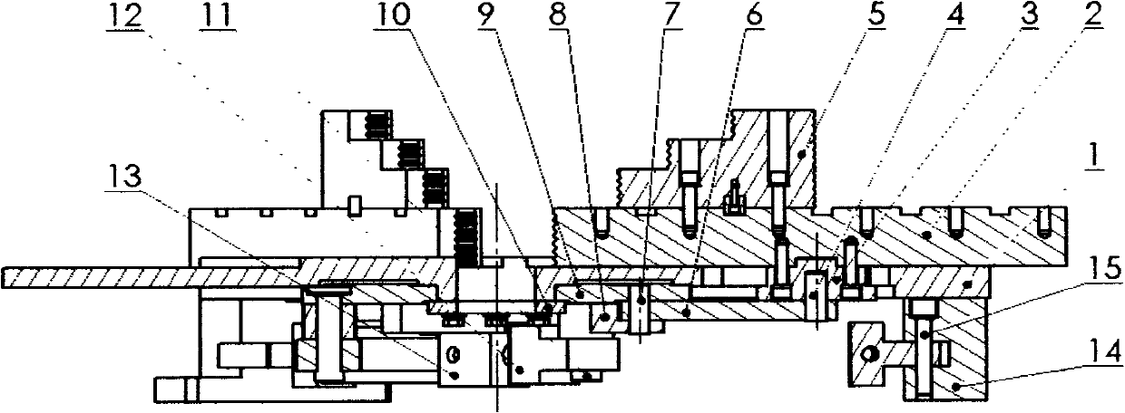
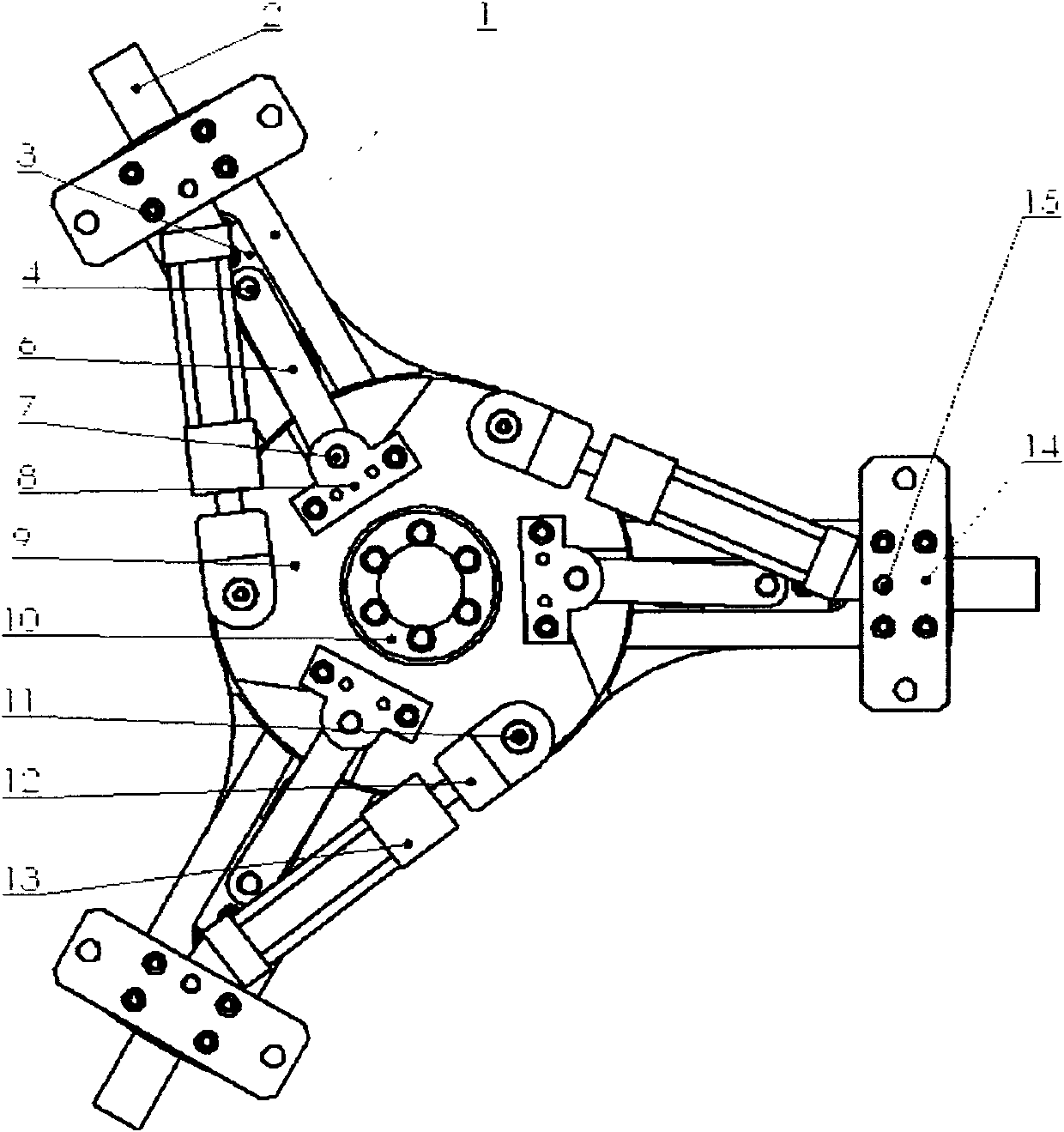
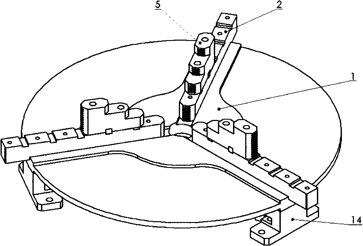
[0021] Referring to the accompanying drawings, the swing rod self-centering power chuck of the present invention will be described in detail below.

[0022] The swing rod self-centering power chuck of the present invention consists of a chuck body 1, a claw seat 2, a slider 3, a slider pin 4, a claw 5, a connecting rod 6, a connecting rod pin 7, a connecting rod seat 8, Flange plate 9, circular pressing plate 10, joint shaft 11, joint 12, oil cylinder 13, oil cylinder seat 14, oil cylinder shaft 15 constitute. The flange 9 is installed closely below the chuck body 1 and coaxial with the chuck body 1, the chuck body 1 and the flange 9 can rotate mutually, and the slider 3 is installed in the slot on the chuck body 1 And can slide in the slot hole, the slider pin 4 is fixed under the slider 3, and is inserted into the hole at one end of the connecting rod 6 with a clearance fit, and the hole at the other end of the connecting rod 6 is fitted on the connecting rod pin 7 with clea...


PUM


Abstract

The invention relates to a self-centering power chuck for a swing rod, which comprises a chuck body, a clamping jaw seat, a slider, a slider pin, clamping jaws, a plurality of connecting rods, a connecting rod pin, a connecting rod seat, a flange plate, a round pressing plate, a joint shaft, a joint, an oil cylinder, an oil cylinder seat and an oil cylinder shaft. Linear movement of a rod of the oil cylinder is transformed into circumferential movement of the flange plate, circumferential movement of the flange plate is transformed into linear movement of the matched clamping jaws along a circumferential radiant line through the connecting rods circumferentially and evenly distributed, and the clamping jaws synchronously move, so that a workpiece is pushed to a circle center until being clamped. Compared with the prior art, the self-centering power chuck has the advantages of simple structure, convenience in machining, low machining cost, small axial size and large travel of the clamping jaws.

Description

technical field [0001] The invention relates to a chuck used on a machine tool, in particular to a swing rod self-centering power chuck. Background technique [0002] At present, most of the self-centering manual chucks used on various machine tools are coil wire-bevel gear pair or screw pair-bevel gear pair structure. The processing costs of the coil wire, screw pair and bevel gear pair are high, and the disc The claw stroke of the wire-bevel gear pair structure is small; most of the self-centering power chucks are wedge-shaped structure, the structure is complex, the axial dimension is large, and the stroke of the claw is also small. Contents of the invention [0003] The purpose of the present invention is to provide a swing rod self-centering power chuck for the above-mentioned deficiencies in the prior art. The swing rod self-centering power chuck has a simple structure, convenient processing, material saving, low processing cost, and The stroke is large, the clampin...

Claims


Application Information

Patent Timeline
Patent Type & Authority Applications(China)
IPC IPC(8): B23B31/10B23B31/30
Inventor 贺自清
Owner 贺自清
Why Eureka
Try Eureka