Liquid discharge head, liquid discharge apparatus employing the same, and recording device

A liquid nozzle and liquid technology, which can be used in inking devices, printing, etc., can solve problems such as changes in ejection characteristics, and achieve the effect of improving recording accuracy

Active Publication Date: 2015-01-14
KYOCERA CORP
View PDF10 Cites 1 Cited by
  • Summary
  • Abstract
  • Description
  • Claims
  • Application Information

AI Technical Summary

Problems solved by technology

[0008] However, in the liquid ejection head described in Patent Document 1, for example, when it is desired to increase the driving frequency for driving the displacement element, or to increase the displacement amount of the displacement element, or to reduce the size of the area connected to the common flow path in order to further improve resolution, When the gap between the liquid pressurization chambers or the cross-sectional area of ​​the common flow path is reduced for miniaturization, the pressure applied to the liquid in the liquid pressurization chamber is transmitted to the common flow path, causing the liquid in the common flow path to resonate While standing waves are generated in the common flow path
[0009] Also, if a standing wave is generated, its pressure will be transmitted to the liquid pressurization chamber, causing fluctuations in the discharge characteristics
In particular, the change in ejection characteristics due to the influence of standing waves is periodic, and when it is used for printing, the periodic effect will be reflected on the image, which may be noticeable

Method used


Image

  • Liquid discharge head, liquid discharge apparatus employing the same, and recording device
  • Liquid discharge head, liquid discharge apparatus employing the same, and recording device
  • Liquid discharge head, liquid discharge apparatus employing the same, and recording device

Examples


Embodiment

[0148] A liquid ejection head in which the shape of the common channel 205a was changed was manufactured, and the relationship between the resonance frequency of the primary standing wave and the variation in ejection speed was evaluated.

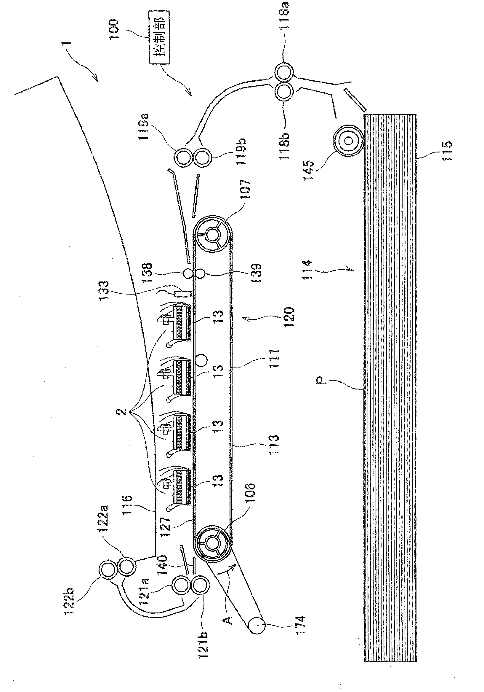
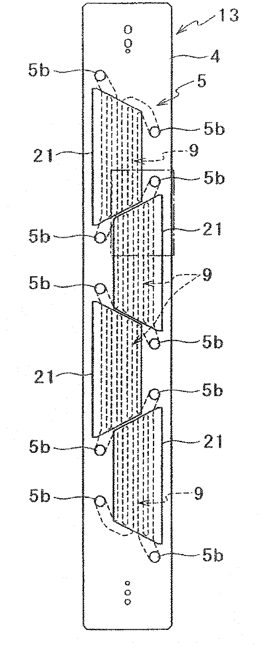
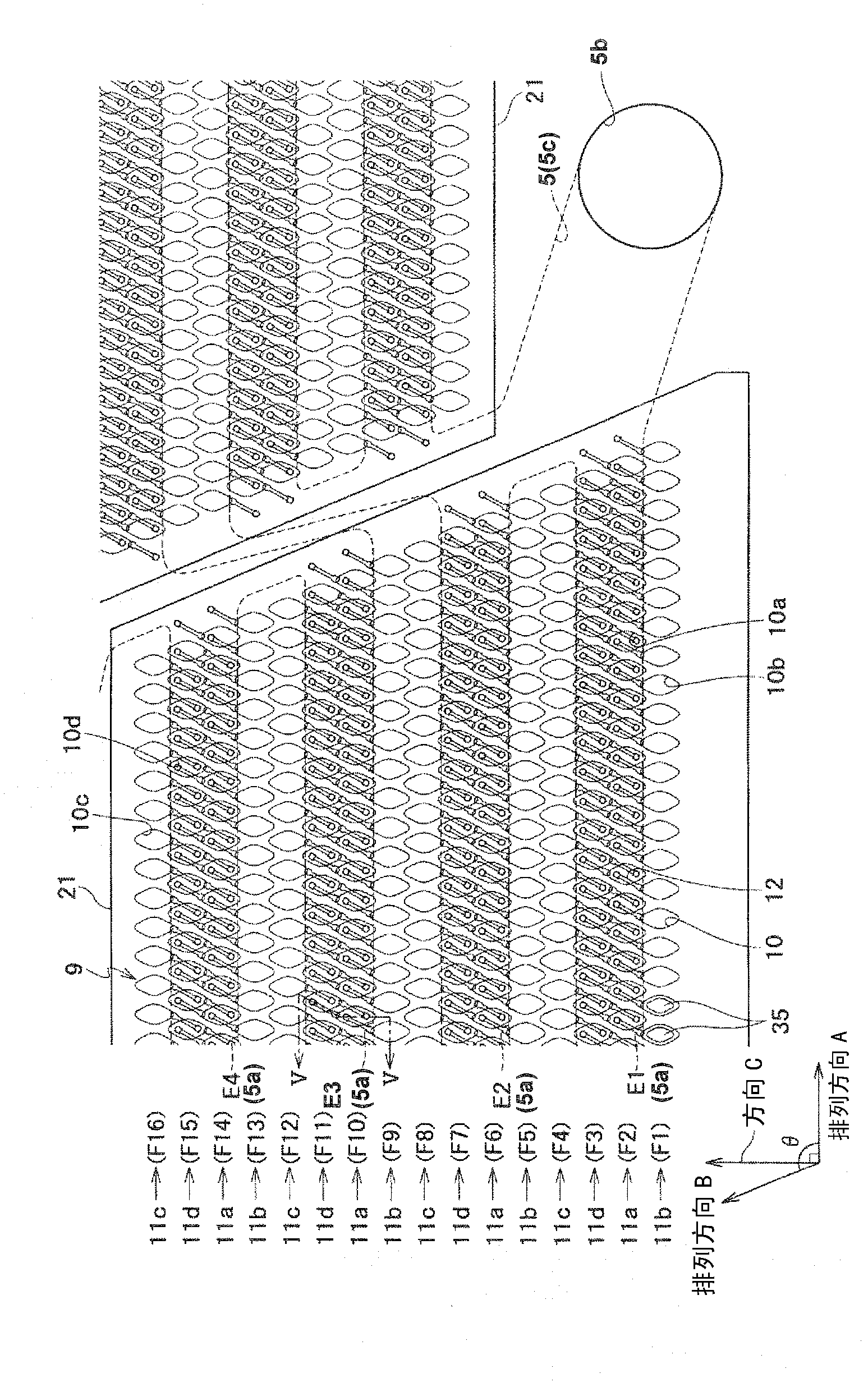
[0149] Figure 8 (a)~(f) and Figure 9 (a) to (e) are schematic diagrams of the common flow path of the liquid jet heads No. 1 to 11 after the test. The basic structure of these common flow paths are the same as figure 2 The liquid ejection head body 13 shown is the same.


PUM


Abstract

Providing is a liquid discharge head less susceptible to a standing wave occurred in a shared flow path; a liquid discharge device using the liquid discharge head; and a recording apparatus. The liquid discharge head includes a plurality of liquid discharge pores; a plurality of liquid pressing chambers 210 respectively connected to the plurality of liquid discharge pores; a shared flow path 205a being long in one direction and being linked the plurality of liquid pressing chambers 210; a liquid supply path 205c which is connected to both ends of the shared flow path 205a, and has a larger cross-sectional area than the shared flow path 205a; and a plurality of pressing parts for respectively pressing liquid in the plurality of liquid pressing chambers 10. The cross-sectional area of a middle segment of the shared flow path 205a is smaller than the cross-sectional area of that of each of both end segments thereof.

Description

technical field [0001] The present invention relates to a liquid ejection head that ejects liquid, a liquid ejection device using the liquid ejection head, and a recording device that prints an image using the liquid ejection device. Background technique [0002] In recent years, inkjet printers, inkjet plotters, etc. have utilized inkjet recording method printing devices, which are not only used in printers for general consumers, but also widely used in, for example, the formation of electronic circuits and liquid crystal displays. Industrial use in the manufacture of color filters and the manufacture of organic EL displays. [0003] In such an inkjet printing device, a liquid ejection head for ejecting liquid is mounted as a print head. In this type of print head, generally, a method is known in which a heater is provided as a pressurizing device in an ink flow path filled with ink, and the ink is heated by the heater to make it boil. The thermal head method in which the...

Claims


Application Information

Patent Timeline
Patent Type & Authority Patents(China)
IPC IPC(8): B41J2/045B41J2/055B41J2/16
CPCB41J2002/14306B41J2002/14459B41J2002/14225B41J2002/14419B41J2002/14217B41J2202/20B41J2/14209
Inventor 松元步穗积大辅
Owner KYOCERA CORP
Why Eureka
Try Eureka