
Adjustable amplification circuit

A technology of amplifying circuits and circuits, applied in power amplifiers, improving amplifiers to improve efficiency, etc., can solve the problems of operation adjustment, poor slew rate improvement, and insufficient supply, so as to improve the overall performance and solve the problem of driving dynamics. The effect of insufficient capacity and increased slew rate

Inactive Publication Date: 2012-07-04
NOVATEK MICROELECTRONICS CORP
View PDF6 Cites 5 Cited by
  • Summary
  • Abstract
  • Description
  • Claims
  • Application Information

AI Technical Summary

Problems solved by technology

In this case, this method of strengthening the bias current for a fixed period will cause many problems
[0006] For example, for an operational amplifier with relatively small internal capacitance, the enhanced bias current will continue to be supplied to the operational amplifier even if the internal capacitance has stored enough charge, and the enhanced bias current will be in vain. Wasted until the end of a fixed period, the result is a lot of extra power consumption, which is not good for electronic devices that need to save power
In contrast, for an operational amplifier with a large internal capacitance, if it only provides an enhanced bias current for a fixed period, it will not be able to provide enough charge, so that the effect of increasing the slew rate will not be good, and the result will be reversed. Insufficient phenomenon
[0007] To sum up, the existing technology increases the slew rate by strengthening the bias current within a fixed period, but it is actually impossible to make proper operation adjustments in response to different operating environments and device requirements.

Method used


Image

  • Adjustable amplification circuit
  • Adjustable amplification circuit
  • Adjustable amplification circuit

Examples


Embodiment Construction

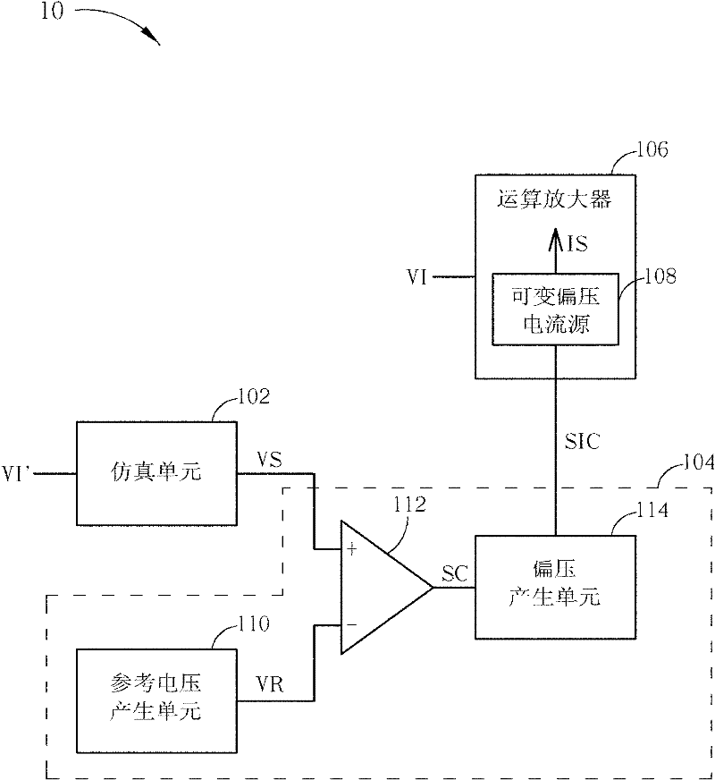
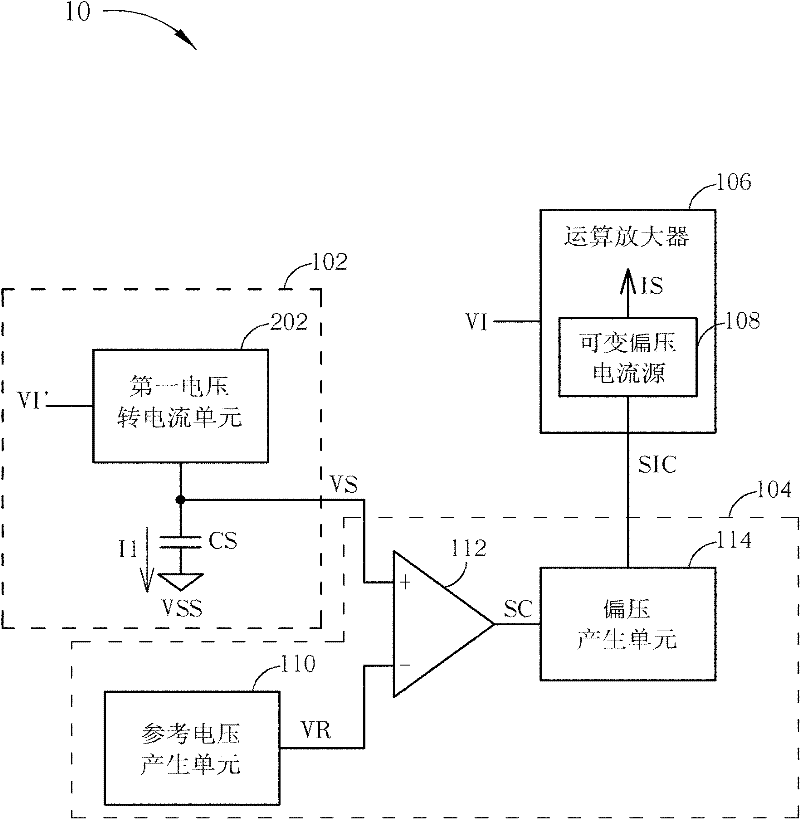
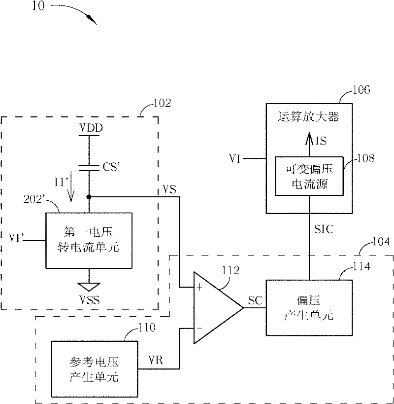
[0045] Please refer to figure 1 , figure 1 It is a schematic diagram of an amplifying circuit 10 according to an embodiment of the present invention. The amplifying circuit 10 includes an emulation unit 102 , a bias control unit 104 and an operational amplifier 106 . The operational amplifier 106 includes a variable bias current source 108 for providing a variable bias current IS for the operational amplifier 106 . The variable bias current IS is available to each stage of the operational amplifier 106 , preferably through at least one input stage of the operational amplifier 106 . The operational amplifier 106 can be any type of operational amplifier, such as a rail-to-rail amplifier, but not limited thereto. The simulation unit 102 and the bias control unit 104 can cooperate to flexibly apply a preferred or even optimized bias to the variable bias current source 108 according to the type of the operational amplifier 106 and the applied operating environment.

[0046] Spe...


PUM


Abstract

The invention discloses an adjustable amplification circuit, which comprises an operational amplifier, a simulation unit and a bias control unit, wherein the operational amplifier comprises a variable bias current source which is used for supplying a variable bias current to the operational amplifier; the simulation unit is used for simulating the operation characteristic of the operational amplifier and converting a simulation input voltage into a simulation output voltage; and the bias control unit is used for generating a bias control signal to the variable bias current source according to the simulation output voltage to adjust the size of the variable bias current.

Description

technical field [0001] The invention relates to an amplifying circuit, in particular to an adjustable amplifying circuit capable of adaptively controlling bias current. Background technique [0002] An operational amplifier is an important circuit component in various electronic circuits. Circuit designers can often use operational amplifiers to implement many different operational functions. For example, in the driving circuit of the liquid crystal display, the operational amplifier can be applied as an output buffer, which charges and discharges the load (that is, liquid crystal) according to the analog signal output by the previous digital-to-analog converter to drive the liquid crystal display corresponding pixel unit. However, as the size and resolution of liquid crystal displays increase, the amount of data output per unit time by the driving circuit of the liquid crystal display is also increasing. Therefore, the response speed of the operational amplifier, that is,...

Claims


Application Information

Patent Timeline
IPC IPC(8): H03F3/20H03F1/02
Inventor 许筱妊林家弘洪炜翔
Owner NOVATEK MICROELECTRONICS CORP
Learn More