
Cavitation erosion detection method based on acoustic emission

A detection method and acoustic emission technology, which is applied in the direction of using acoustic emission technology for material analysis and processing detection response signals, etc., which can solve problems such as unclear correspondence and difficult estimation of cavitation

Inactive Publication Date: 2012-07-04
TSINGHUA UNIV
View PDF2 Cites 15 Cited by
  • Summary
  • Abstract
  • Description
  • Claims
  • Application Information

AI Technical Summary

Problems solved by technology

At present, research on cavitation state monitoring has been paid attention to. Common cavitation monitoring methods monitor cavitation phenomena through noise and structural vibration and other physical quantities to monitor cavitation indirectly. On-line Monitoring Method and Diagnosis Device for Corrosion Damage" provides an indirect cavitation monitoring method by monitoring the cavitation coefficient of fluid machinery, the pressure pulsation in the flow channel, the energy characteristics of fluid machinery, and the working water head. Monitoring and Diagnosis System" (Source: Water Conservancy and Hydropower Technology, 2002, 33(7): 17-20) uses pressure pulsation, efficiency and cavitation noise to monitor cavitation indirectly, and the literature "Cavitations monitoring and diagnosis of hydropower turbine online based on vibration and ultrasound acoustic" (Source: Proceedings of the Sixth International Conference on Machine Learning and Cybernetics, 2007: 19-22) monitors cavitation indirectly using cavitation-induced vibration and ultrasound pairs; however these are associated with cavitation The corresponding relationship between the physical quantities and cavitation erosion is not clear, so it is difficult to accurately estimate the state of cavitation erosion by indirect monitoring methods based on these physical quantities

Method used


Image

  • Cavitation erosion detection method based on acoustic emission
  • Cavitation erosion detection method based on acoustic emission
  • Cavitation erosion detection method based on acoustic emission

Examples


Embodiment Construction

[0025] The present invention will be further described below in conjunction with the accompanying drawings and embodiments.

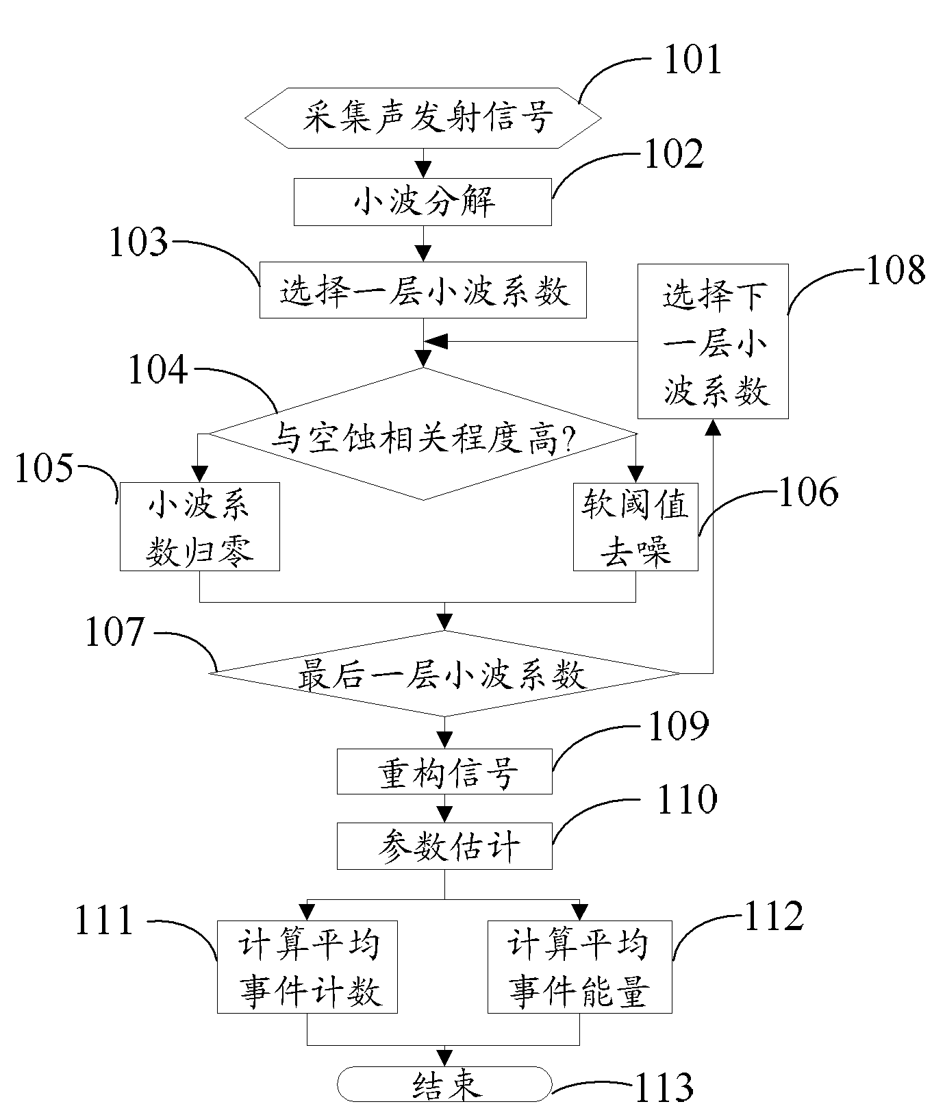
[0026] Such as figure 1 As shown, it is a processing flowchart of the acoustic emission-based cavitation detection method of the present invention.

[0027] In a preferred embodiment of the present invention, in the process of cavitation detection, it is first necessary to use an acoustic emission sensor to measure the acoustic emission signal generated during the cavitation process to obtain a signal containing the acoustic emission caused by the cavitation. After the signal containing the acoustic emission caused by the cavitation is obtained, the cavitation detection method based on the acoustic emission of the present invention is used to detect the cavitation.

[0028] Step 101: Use the acoustic emission sensor to collect the acoustic emission signal per unit time length during the cavitation development process, the specific process is as follows...


PUM


Abstract

The invention discloses a cavitation erosion detection method based on acoustic emission, which comprises the following steps: utilizing an acoustic emission sensor to collect an acoustic emission signal in unit time length during cavitation erosion development; performing wavelet decomposition on the acoustic emission signal according to set layer number to obtain a wavelet coefficient and relevant degree of the cavitation erosion and frequency range where the wavelet coefficient is located, and denoising the wavelet coefficient according to the relevant degree and the set layer number; performing signal reconstruction by utilizing the wavelet coefficient after denoising, and obtaining a reconstruction signal; setting parameter estimating threshold and counting time interval of the reconstruction signal; calculating acoustic emission event number and acoustic emission even average energy of the reconstruction signal; and judging plastic deformation and mass loss condition during cavitation erosion development according to the acoustic emission even number and the acoustic emission even average energy. The cavitation erosion detection method based on the acoustic emission performs denoising according to the characteristics of the acoustic emission signal and utilizes a simple estimating parameter to represent the development condition of plastic deformation and mass loss during cavitation erosion.

Description

technical field [0001] The invention relates to a method for directly detecting cavitation erosion, in particular to a method for detecting cavitation erosion based on acoustic emission technology. Background technique [0002] When the local pressure of the liquid is low enough, cavitation will occur; the process of causing damage to the surface of the solid material when the cavitation collapses is called cavitation erosion. Cavitation is a common form of damage to fluid machinery: slight cavitation causes the surface of the material to lose its luster and produces pits; severe cavitation causes the material to become loose or even fall off, affecting the operating state of the fluid machinery. First of all, in order to avoid severe cavitation, it is necessary to monitor the occurrence of cavitation and adjust the operating status of hydraulic machinery; secondly, to avoid severe cavitation, it is necessary to repair the surface of fluid machinery before it occurs, and the...

Claims


Application Information

Patent Timeline
IPC IPC(8): G01N29/14G01N29/44
Inventor 何永勇沈再阳
Owner TSINGHUA UNIV
Learn More