
Rotating bracket for wind-tunnel flow-field display test models

A technology of test models and rotating brackets, which is applied in aerodynamic tests, machine/structural component tests, and measuring devices. It can solve the problems of large human injuries, toxicity, and weakness, and achieve improved efficiency and accuracy and simple structure. , The effect of convenient processing

Active Publication Date: 2012-07-04
SOUTHEAST UNIV
View PDF8 Cites 15 Cited by
  • Summary
  • Abstract
  • Description
  • Claims
  • Application Information

AI Technical Summary

Problems solved by technology

[0004] The building structure model in the actual wind tunnel test is usually asymmetrical, and most of the test conditions need to consider different wind directions in the design of the test conditions. In addition, the pulse laser used in the current PIV test is fixed and difficult to adjust. The traditional method is that the test personnel enter In the wind tunnel, the required wind angle of attack can be achieved by moving the bracket and the model several times
However, due to the bulkiness of the model support and the weak reference for adjustment, especially when a variety of test wind attack angles are set, this traditional method makes it difficult to guarantee the adjustment accuracy of the model wind attack angle
In addition, the tracer particles spread in the PIV test are produced by smoke, which has certain toxicity, and long-term exposure to the tracer particle environment will cause great harm to the human body

Method used


Image

  • Rotating bracket for wind-tunnel flow-field display test models
  • Rotating bracket for wind-tunnel flow-field display test models
  • Rotating bracket for wind-tunnel flow-field display test models

Examples


Embodiment Construction

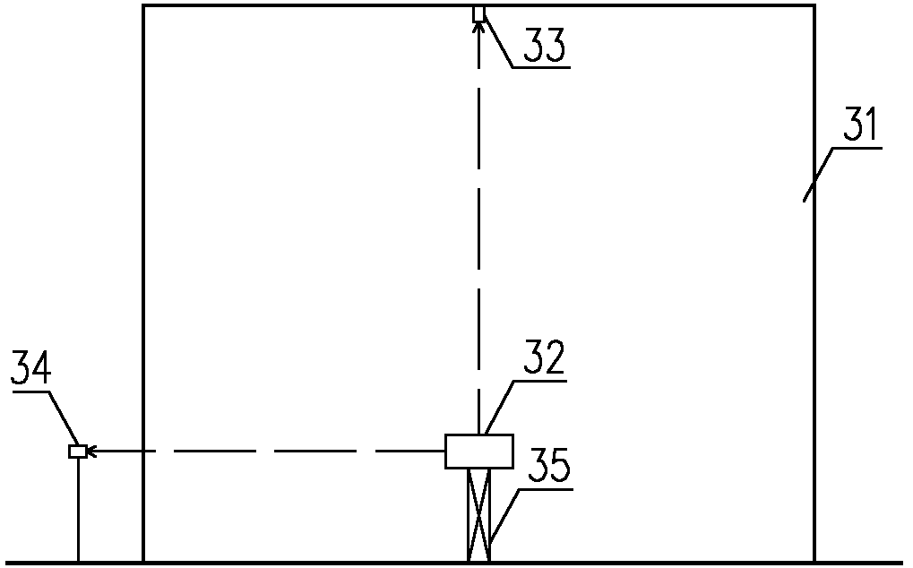
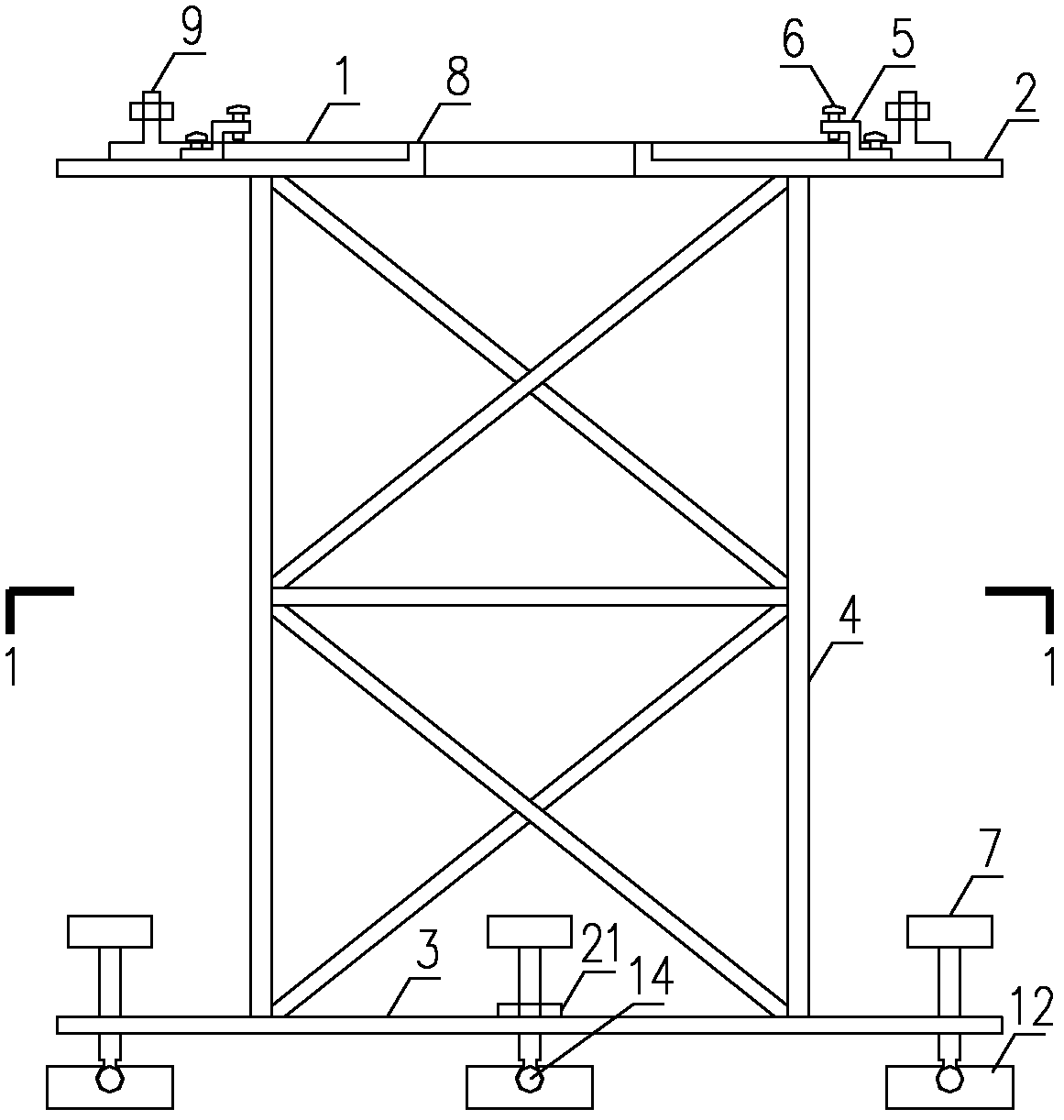
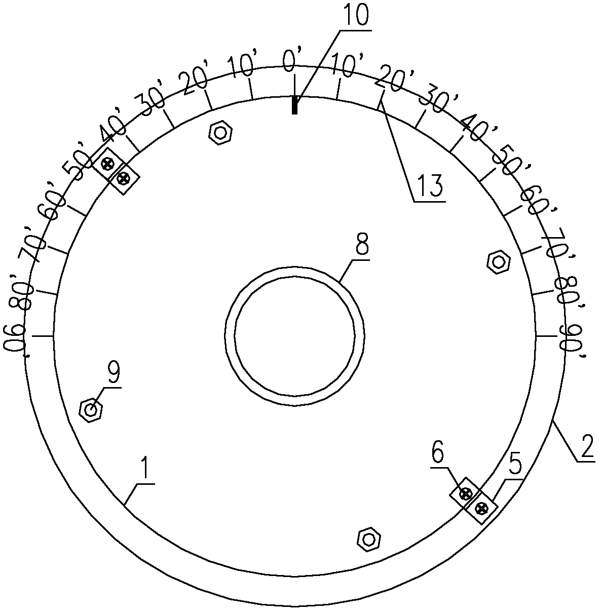
[0026] A wind tunnel flow field display test model rotating bracket, comprising: a bottom plate 3 and a top plate 2 parallel to each other, a supporting truss 4 is provided on the bottom plate 3 and the top plate 2, a central circular hole is provided on the top plate 2, and a central circular hole is A flange 8 is arranged on the circumference, and a rotating plate 1 is set on the flange 8. A scale pointer 10 and a number of model fixing bolts 9 are arranged on the rotating plate 1. Scale line 13 to accurately locate the rotation angle of the model.

[0027] The top plate 2 is provided with a limit button 5, and one end of the limit button 5 is fixedly connected with the top plate 2, and the other end is located above the top surface of the edge of the rotating plate 1, and the limit button 5 is threaded with a limit fixing bolt 6. A first level 21, a second level 22, and a height adjustment bolt 7 are arranged on the bottom plate 3, the first level 21 and the second level 22...


PUM


Abstract

The invention discloses a rotating bracket for wind-tunnel flow-field display test models, and the rotating bracket is provided for solving the problems that in a wind-tunnel flow-field display test, the adjustment on the levelness and rotating angle of the traditional test model is inconvenient and not high in precision. A bottom plate of the bracket is provided with a height adjusting bolt and a level instrument so as to meet the requirements on the levelness of the test model; the edge of a top plate of the bracket is provided with an angle scale line, and a rotating plate is arranged above the top plate, then the model can be rotated quickly and accurately so as to adjust the test model to a required wind attack angle; and besides the wind-tunnel flow-field display test, the bracket also takes the demands of a pressure measuring test for wind tunnels into consideration, holes are arranged in the centers of the top plate and the rotating plate so as to facilitate the connection between a pressure measuring pipe at the bottom of the model and a pressure measuring device below a floor board of a wind tunnel. The rotating bracket disclosed by the invention can be used for solving the problem that in a wind-tunnel flow-field display test, the manual adjustment on the levelness and rotating angle of a model is poor in precision; and the rotating bracket not only can be applied to wind-tunnel flow-field display tests on pure building structure scaled models in wind tunnels, but also can be applied to synchronous pressure measuring tests.

Description

technical field [0001] In the wind tunnel flow field display test, it is usually necessary to photograph the streamlines and velocity field distribution on the surface of the scale model of the building structure under various wind direction angles, so the model needs to be rotated many times in the test to simulate different wind direction angles. The invention is a rotating support for a wind tunnel flow field display test model which is convenient for adjusting the angle of the model, and effectively improves the efficiency and precision of angle adjustment. Background technique [0002] Flow field display technology is an important part of fluid mechanics experiments, among which Particle Image Velocimetry (abbr. PIV) is based on the traditional flow field display technology, using the research results of optical technology and image analysis technology to develop rapidly A new type of flow field testing method that has grown up. The important feature of PIV technology ...

Claims


Application Information

Patent Timeline
IPC IPC(8): G01M9/04
Inventor 董欣叶继红
Owner SOUTHEAST UNIV
Learn More