
Coplanar sensor and manufacturing method thereof

A manufacturing method and sensor technology, applied in the direction of using electric/magnetic devices to transfer sensing components, manufacturing microstructure devices, piezoelectric devices/electrostrictive devices, etc., can solve the problem of warping and overlapping of fixed arms 52 and extension arms 64 Reduced area, reduced effective capacitance, etc.

Inactive Publication Date: 2012-07-04
PIXART IMAGING INC
View PDF12 Cites 0 Cited by
  • Summary
  • Abstract
  • Description
  • Claims
  • Application Information

AI Technical Summary

Problems solved by technology

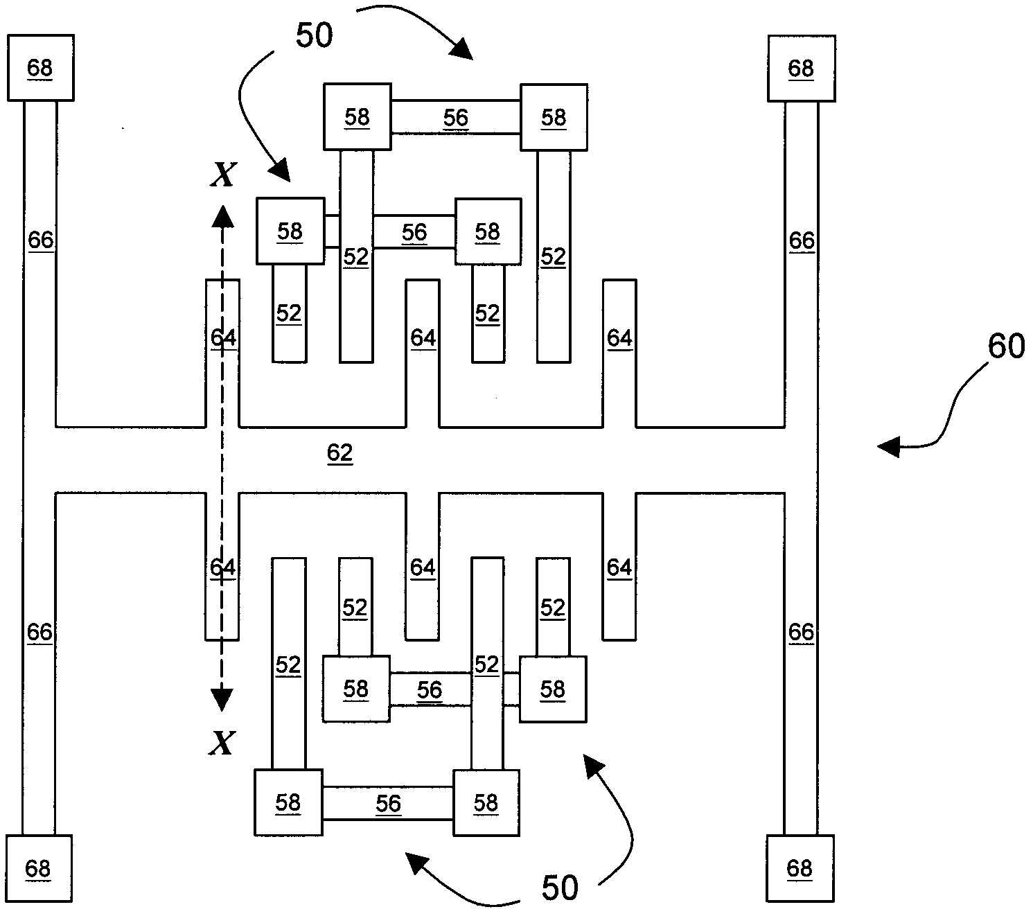
[0005] see figure 2 (this is from figure 1 X--X cross-section of X--X cross-sectional view obtained from looking to the right), since both the fixed arm 52 and the extension arm 64 are suspended structures, it is easy to cause warping in the semiconductor process, and at this time the fixed arm 52 and the extension arm 64 overlap The area is significantly reduced, resulting in a lower effective capacitance value

Method used


Image

  • Coplanar sensor and manufacturing method thereof
  • Coplanar sensor and manufacturing method thereof
  • Coplanar sensor and manufacturing method thereof

Examples


Embodiment Construction

[0059] The icons in this manual are schematic, and their dimensions are not completely drawn to scale.

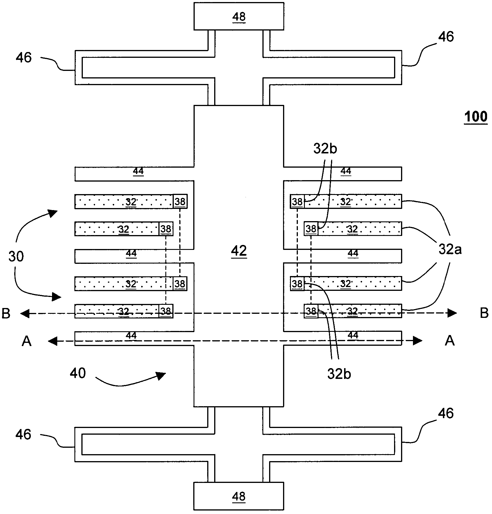
[0060] see image 3, in the first embodiment of the present invention, the MEMS structure 100 of the coplanar sensor includes at least one fixed structure 30 and one movable structure 40 . The moving structure 40 includes a main body 42, an extension arm 44, a connecting portion 46 and a fixed portion 48, which are connected to each other; wherein the main body 42, the extending arm 44, and the connecting portion 46 are suspended structures, and the fixed portion 48 is a fixed structure, which means that except The fixed part 48 is fixed on the lower base (not shown), and the body 42, the extension arm 44 and the connecting part 46 connected to each other are suspended. In one embodiment, the connecting portion 46 is a spring, which can be stretched elastically. The fixing structure 30 includes a plurality of fixing arms 32 . Each fixing arm 32 itself is suspended, and ha...


PUM


Abstract

The invention relates to a coplanar sensor. The coplanar sensor comprises a fixed structure and a movable structure, wherein the fixed structure comprises fixed arms and fixed ends which are connected; each fixed arm is provided with a supporting end and a suspension end; each supporting end is connected with the fixed end; each suspension end is suspended; the movable structure at least comprises a body and extension arms, wherein the body is connected with the extension arms; and the supporting end of each fixed arm is more close to the body than the suspension end.

Description

[0001] This application is a divisional application of the application with the application number 200810108149.6 and the title of the invention "Same Plane Sensor and Manufacturing Method" submitted on May 27, 2008. technical field [0002] The invention relates to a coplanar sensor and a manufacturing method, in particular to a coplanar sensor and a manufacturing method capable of reducing the influence of residual stress on a process. Background technique [0003] The function of the in-plane sensor is to sense the change of the capacitance value between the two electrodes due to the change of the plane distance, so as to generate a corresponding signal, which can be applied to making an accelerometer or a gyro sensor, etc., for example. Regarding the prior art of in-plane sensors and their manufacturing methods, for example, refer to US Patent Nos. 5,326,726, 5,847,280, 5,880,369, 6,877,374, and 6,892,576. [0004] Each of the above-mentioned prior art has the same probl...

Claims


Application Information

Patent Timeline
Patent Type & Authority Applications(China)
IPC IPC(8): G01D5/241B81B3/00B81C1/00
Inventor 王传蔚李昇达
Owner PIXART IMAGING INC
Learn More