Direct cooling water system for cooling machines

A cooling water system and cooling machine technology, which is applied in the direction of processing discharged materials, furnaces, lighting and heating equipment, etc., can solve the problems of complex cooling machine structure, increased factory investment, and inconvenient production and maintenance, so as to facilitate equipment installation and The effects of worker operation, reduced initial investment, and simple structure

Inactive Publication Date: 2012-07-04
GUIYANG AL-MG DESIGN & RES INST
View PDF6 Cites 2 Cited by
  • Summary
  • Abstract
  • Description
  • Claims
  • Application Information

AI Technical Summary

Problems solved by technology

[0003] The technical problem to be solved by the present invention is: to provide a cooling machine direct cooling water system to overcome the disadvantages of the existing technology such as complex structure of the cooling machine, difficulty in installation, increased investment in the factory, and a lot of inconvenience to production and maintenance.

Method used


Image

  • Direct cooling water system for cooling machines
  • Direct cooling water system for cooling machines
  • Direct cooling water system for cooling machines

Examples


Embodiment Construction

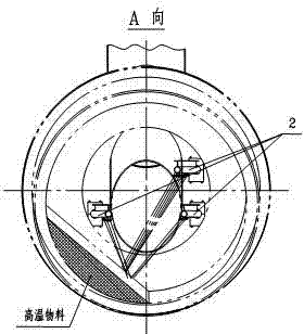
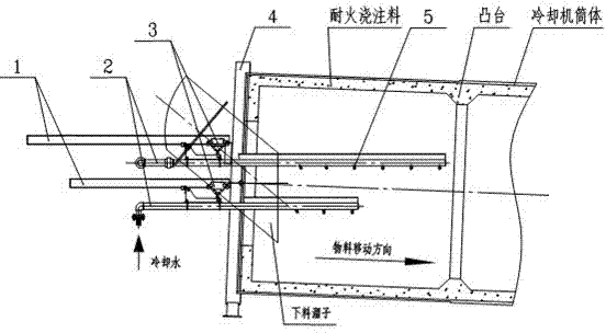
[0009] Embodiment of the present invention: The components of the present invention are: slide rail 1 , cooling water pipeline 2 , pulley 3 , tail cover 4 , nozzle 5 . The slide rail 1 is fixedly installed, and the cooling water pipeline 2 extends into the cylinder body of the cooler through the opening on the tail cover 4, and several nozzles 5 are installed in the cylinder body part. The outer part of the cylinder of the cooling water pipeline 2 is connected with the pulley 3 and installed on the slide rail 1 . The cooling water pipeline 2 and the nozzle 5 can be pulled out from the cooling machine barrel through the slide rail 1 and the pulley 3, so as to facilitate maintenance when necessary. There is a refractory castable in the cooling machine cylinder to avoid direct contact of high temperature materials with the cylinder wall. A boss is built at a certain position on the refractory castable. The function of the boss is to prevent the material and cooling water from m...


PUM


Abstract

The invention discloses a direct cooling water system for cooling machines. The direct cooling water system is characterized in that a cooling water pipe (2) extends into a cooling-machine barrel through a hole arranged on a tail cover (4), and the part of the cooling water pipe (2), which is in the barrel, is provided with a nozzle (5); and the part of the cooling water pipe (2), which is outside the barrel, is connected with a pulley (3), and the pulley (3) is arranged on a guide rail (1). The invention provides a direct cooling water system for cooling machines used in the chemical industry, the cement engineering and the metallurgical engineering and the like; the direct cooling water system is simple in structure; through adoption of the direct cooling water system, the initial investments of factories can be reduced, the installation of equipment and the operation of workers are facilitated, and operation and maintenance cost can be lowered.

Description

technical field [0001] The invention relates to a direct cooling water system on the tail cover of a cooling machine. Background technique [0002] In chemical, cement and metallurgical projects, materials are calcined at a high temperature in a rotary kiln, and the temperature is relatively high, so they generally need to be cooled in the cylinder of the cooling machine. The traditional direct cooling water system of the cooler only injects water through a small hole in the tail cover, and the cooling of the material is not obvious. Therefore, an indirect cooling water system is added, that is, multiple cooling water jackets are arranged along the axial direction of the cooler barrel, and the purpose of cooling the material in the barrel is achieved by spraying water on the outer wall of the cooler barrel. This has resulted in a complex structure of the cooling machine, difficulty in installation, increased investment in the factory, and brought a lot of inconvenience to p...

Claims


Application Information

Patent Timeline
Patent Type & Authority Applications(China)
IPC IPC(8): F27D15/02
Inventor 高军永
Owner GUIYANG AL-MG DESIGN & RES INST
Why Eureka
Try Eureka