
Combustion flame diagnostic method

A diagnostic method and flame combustion technology, which is applied in the direction of combustion methods, combustion chambers, combustion equipment, etc., can solve the problems of not being able to identify whether the flame exists and its stability, and prone to false alarms

Active Publication Date: 2012-07-04
IND TECH RES INST
View PDF4 Cites 26 Cited by
  • Summary
  • Abstract
  • Description
  • Claims
  • Application Information

AI Technical Summary

Problems solved by technology

However, common radiant light energy (UV / VIS / IR) flame detectors can only detect the presence or absence of flames, and need to set static thresholds and have no spatial information, so false alarms are prone to occur. Improved digital flame detectors The device still cannot effectively solve the misjudgment of flame presence or absence caused by flame drift. A more novel method is a full-furnace image monitoring system that uses combustion images and microprocessor computing capabilities, but the full-furnace image monitoring system is for the entire furnace Judging or monitoring the combustion status, unable to identify whether the flame exists and its stability

Method used


Image

  • Combustion flame diagnostic method
  • Combustion flame diagnostic method
  • Combustion flame diagnostic method

Examples


Embodiment Construction

[0049] The description of the present invention provides different examples to illustrate the technical features of different implementations of the present invention. Wherein, the configuration of each element in the embodiment is for illustration, not for limiting the present invention. Moreover, part of the symbols in the figures in the embodiments is repeated, for the sake of simplicity of description, it does not imply the relationship between different embodiments.

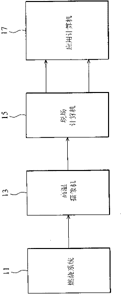
[0050] The embodiment of the invention discloses an image-based combustion process monitoring and diagnosis method. The image-based combustion process monitoring and diagnosis method of the embodiment of the present invention uses an external or plug-in image capture device to capture the flame image in the furnace under a high-temperature environment, and conducts the process according to the characteristics obtained by analyzing the flame image. Flame combustion monitoring to diagnose the combustion state...


PUM


Abstract

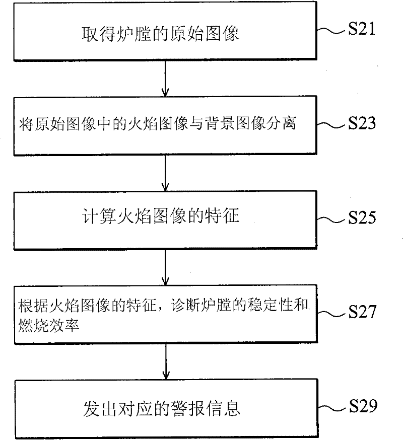
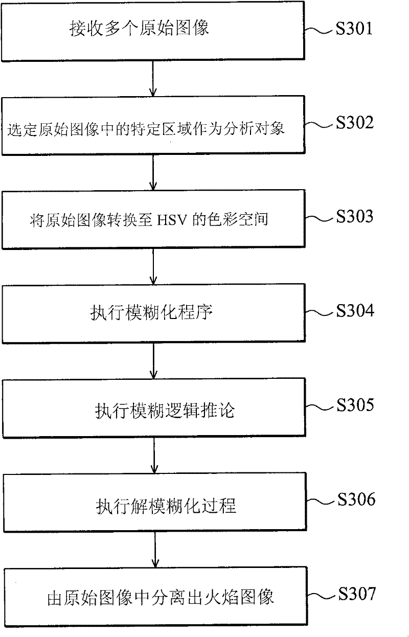
The present invention provides a combustion flame diagnostic method comprising the steps of: utilizing an image capturing device to obtain an original image of a combustion chamber used for executing a combustion technology, wherein the original image comprises a flame image and a background image; utilizing a flame recognition technology to separate the flame image and the background image in the original image; calculating characteristics of the flame image; and diagnosing stability and combustion efficiency of the combustion chamber according to the characteristics of the flame image.

Description

technical field [0001] The invention relates to an image-based process monitoring and diagnosis method, and in particular to a flame image-based combustion process monitoring and abnormal phenomenon and cause diagnosis method. Background technique [0002] The boiler system is currently the source of power and heat for process production in chemical plants, power plants or traditional manufacturing industries. However, due to the impact of international oil price fluctuations and rising environmental awareness in recent years, as well as the increasing emphasis on industrial safety, the development is more efficient. A combustion monitoring system that is more in line with environmental protection standards, exhaust gas, and safer to operate has become an important issue in boiler equipment development and combustion process monitoring. [0003] The basic requirement for the operation of industrial combustion systems such as boiler systems is to establish a stable combustion...

Claims


Application Information

Patent Timeline
IPC IPC(8): F23M11/04G06K9/62
Inventor 郑仪诚傅家麟黄嘉弘徐振凯
Owner IND TECH RES INST
Learn More