Cycloid propeller fan

A cycloidal propeller and fan technology, which is applied in the field of cycloidal propeller fans, can solve problems such as complex mechanism, difficult implementation, and insufficient fan shaking angle, so as to achieve high wind speed and avoid interference

Inactive Publication Date: 2014-04-02
NORTHWESTERN POLYTECHNICAL UNIV
View PDF9 Cites 0 Cited by
  • Summary
  • Abstract
  • Description
  • Claims
  • Application Information

AI Technical Summary

Problems solved by technology

[0010] In order to overcome the deficiencies in the prior art, such as insufficient fan shaking angle, inability to realize all-round air blowing, complex mechanism, and great difficulty in realization, the present invention proposes a cycloidal paddle fan, which uses the cycloidal paddle as the blowing mechanism

Method used


Image

  • Cycloid propeller fan
  • Cycloid propeller fan
  • Cycloid propeller fan

Examples


Embodiment Construction

[0036] Describe the present invention below in conjunction with specific embodiment:

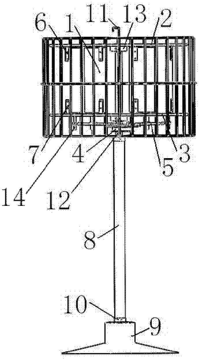
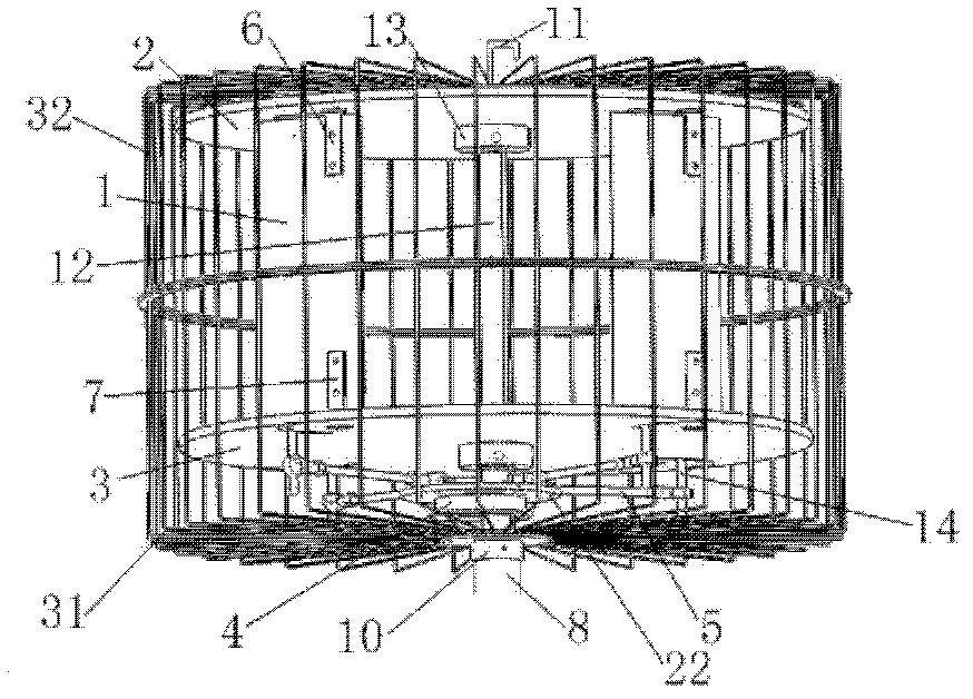
[0037] This embodiment is a cycloidal paddle fan with a cycloidal paddle as a blowing device, including a fan base 9, a driving motor 33 and a blowing mechanism. A fan cover is fixed outside the blowing mechanism for safety. Fan cover is divided into upper fan cover 32 and lower fan cover 31, upper fan cover 32 and lower fan cover 31 are all made of aluminum alloy material, there is a handle 11 in the middle part of upper fan cover 32 tops, convenient mobile fan, upper fan cover 32 and The lower fan cover 31 is connected by a bayonet socket.

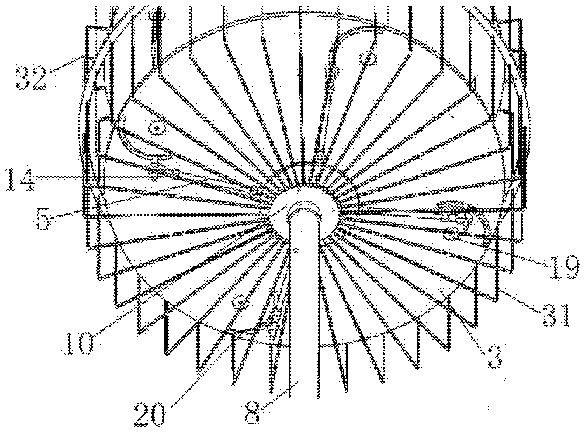
[0038] Refer to attached figure 1 And attached Figure 10 , the drive motor is fixedly installed in the fan base, and is encapsulated by the motor installation wall plate 34, and the power output shaft of the drive motor passes through the motor installation wall plate and is fixedly connected with the fan shaft 12 in the blowing mechanism, thereby dr...


PUM


Abstract

The invention provides a cycloid propeller fan, which includes a fan base, a driving motor and a blowing mechanism; the driving motor is fixed in the fan base, and a power output shaft of the driving motor is connected with a fan rotating shaft in the blowing mechanism and drives the fan rotating shaft to rotate; the blowing mechanism includes blades, the fan rotating shaft, an upper end plate, a lower end plate and an eccentric ring positioning mechanism; and the eccentric ring positioning mechanism includes a control pull rod, an eccentric rotating ring and an eccentric hollow cylinder positioning table. The cycloid propeller fan provided by the invention does not need to shake the head, the blowing direction of a cycloid propeller can be changed by changing the eccentric azimuth angle of the eccentric rotating ring through a steering engine, and the defect that the conventional fan cannot blow in all directions is solved; and the eccentricity of the eccentric rotating ring is adjusted to change the blade attack angles and realize the continuous adjustment on the wind speed of the fan, so that the defect that the existing fan has only fixed gears is overcome, and the demands of different people in different environments can be met.

Description

technical field [0001] The invention relates to the technical field of household electrical appliances, in particular to a cycloid fan. Background technique [0002] At present, most of the electric fans sold in the market are oscillating fans. The oscillating fans have a limited oscillating angle, a small blowing range, cannot blow air to the side and back of the fan, and the oscillating speed is relatively slow. [0003] Chinese patent CN 2463571Y applied for by Zhang Shaoxi discloses a kind of 360 ° annular air supply fan. The shape of the fan blade of this invention is based on the rotating body, the fan blade is an air-supply spiral on the rotating surface of the rotating body, the fan blade is a suction spiral at the upper and lower ends of the rotating body, and the middle part of the fan blade is provided with a reinforcing rib. Partition plate; the rotating shaft is the blade rotating shaft. The purpose of this invention is to provide a 360° annular air supply fan...

Claims


Application Information

Patent Timeline
Patent Type & Authority Patents(China)
IPC IPC(8): F04D25/08F04D29/26F04D29/00
Inventor 胡峪唐继伟宋笔锋宋文萍
Owner NORTHWESTERN POLYTECHNICAL UNIV
Why Eureka
Try Eureka