Apparatus for manufacturing vitreous silica crucible

A glass crucible and manufacturing device technology, applied in the field of vitreous silica crucible manufacturing device, to achieve the effect of easy adjustment

Active Publication Date: 2012-07-04
SUMCO CORP
View PDF4 Cites 3 Cited by
  • Summary
  • Abstract
  • Description
  • Claims
  • Application Information

AI Technical Summary

Problems solved by technology

[0005] On the other hand, when the silicon oxide powder layer is heated and melted, dust such as smoke (silicon oxide vapor) may be generated in the rotating mold.

Method used


Image

  • Apparatus for manufacturing vitreous silica crucible
  • Apparatus for manufacturing vitreous silica crucible
  • Apparatus for manufacturing vitreous silica crucible

Examples


Embodiment Construction

[0054] An embodiment of the vitreous silica crucible manufacturing device of the present invention will be described in detail below with reference to the accompanying drawings.

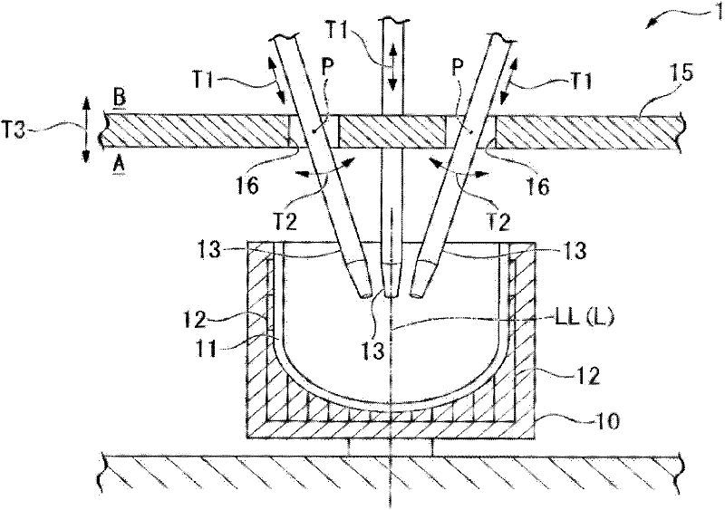
[0055] figure 1 It is a partial schematic diagram of a vitreous silica crucible manufacturing apparatus according to this embodiment, and in the figure, reference numeral 1 is a vitreous silica crucible manufacturing apparatus.

[0056] The vitreous silica crucible manufacturing apparatus 1 of the present embodiment is described as an example of a heat source for manufacturing a vitreous silica crucible with a diameter of 24 inches or more and about 32 to 44 to 50 inches. The device of the conductor is not limited to the type of material to be melted, the diameter of the crucible, the output capacity of the device, and the use as a heat source, and is not limited to the structure.

[0057] The vitreous silica crucible manufacturing apparatus 1 of the present embodiment is divided into a melting cham...


PUM

PropertyMeasurementUnit
diameteraaaaaaaaaa
diameteraaaaaaaaaa

Abstract

Provided is an apparatus for manufacturing a vitreous silica crucible which has a structure which can reduce gaps between a partition wall and electrodes inserted into through-holes formed in the partition wall while enabling electrodes to move to adjust a heating temperature of arc discharge. A plate-shaped partition wall 15 is placed above the rotating mold 10. Electrodes 13 for heating and fusing are inserted into through-holes 16 penetrating in a thickness direction, and are directed toward the rotating mold 10. A rocking unit 40 is provided on an upper side of the partition wall 15 and rocks the electrodes 13 around virtual rocking axes P, and the virtual rocking axes P pass through the through-holes 16.

Description

technical field [0001] The invention relates to a vitreous silica crucible manufacturing device which utilizes a rotary mold method to manufacture a vitreous silica crucible. Background technique [0002] As is well known, the rotary die method is used as a method for manufacturing a vitreous silica crucible for pulling silicon single crystals (for example, refer to Patent Document 1 and Patent Document 2). In this method, a vitreous silica crucible manufacturing apparatus including a rotating mold for depositing silica powder on the inner surface of a bowl while rotating and a plurality of electrodes provided on above the rotary mold. [0003] That is, in this vitreous silica crucible manufacturing apparatus, by rotating the rotary mold around its axis of rotation, silica powder with a specific layer thickness is deposited on the inner surface of the rotary mold to form a vitreous silica powder in the rotary mold. Silica powder constitutes a bowl-shaped silica powder laye...

Claims


Application Information

Patent Timeline
Patent Type & Authority Applications(China)
IPC IPC(8): C03B19/09
CPCC03B19/095C03B20/00
Inventor 須藤俊明岸弘史藤田刚司神田稔
Owner SUMCO CORP
Why Eureka
Try Eureka