
Replacement system and method for power battery box

A technology of power battery and battery box, applied in the direction of power unit, electric power unit, circuit or fluid pipeline, etc., can solve the problems of unfavorable promotion of electric vehicles, inability to replace car batteries, etc., to solve the problem of battery charging environment and solve the problem of replacement. Adaptability, the effect of improving the service life

Inactive Publication Date: 2012-07-04
BEIJING STATE GRID PURUI EXTRA HIGH VOLTAGE POWER TRANSMISSION TECH CO LTD +1
View PDF6 Cites 19 Cited by
  • Summary
  • Abstract
  • Description
  • Claims
  • Application Information

AI Technical Summary

Problems solved by technology

This patent application only discloses the device and method for quick battery replacement, but it does not involve how to charge the battery that is deficient in power. A system that does not match the charging of a depleted battery and the installation of a fully charged battery cannot be called a complete battery replacement system.
[0008] The new application with the application number CN201110096497.8 in 2011 announced a battery replacement system and its replacement method for portable electric vehicles, which solved the problem of being unable to replace the battery of a car and urgently needing to replace the battery while driving, and can directly Replacing Electric Vehicle Batteries
The device is suitable for long-time driving vehicles, but in practical applications, the driver must carry both a fully charged battery and a battery replacement device, which is extremely unfavorable for the promotion of electric vehicles

Method used


Image

  • Replacement system and method for power battery box
  • Replacement system and method for power battery box
  • Replacement system and method for power battery box

Examples


Embodiment Construction

[0043] Below in conjunction with example the present invention is described in detail.

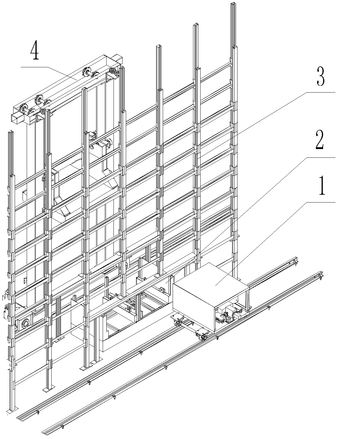
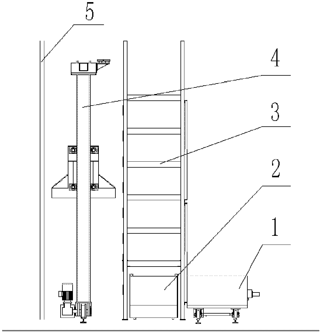
[0044]The invention provides a quick replacement system and method for a power battery box, such as figure 1 As shown in the overall schematic diagram of the replacement system, the system consists of four parts, manipulator 1 for loading and unloading batteries from the vehicle, battery rack 3 for storing and charging the battery box, shuttle car 2 under the battery rack for temporarily storing the batteries required by the manipulator, and the shuttle car The stacker 4 that picks and places the battery on the battery rack and places the battery on the battery rack, of which two manipulators 1 are located at the front of the battery rack 3, two shuttle cars 2 are located under the battery rack, one battery rack 3, and the stacker 4. One is located at the rear of the battery rack 3.

[0045] Such as Figure 4 As shown in the structural diagram of the manipulator, the manipulator 1 includ...


PUM


Abstract

The invention provides a replacement system and a replacement method for a power battery box and solves the problems of replacement adaptability, using of a battery rack, charging environment of a battery and rapid replacement of the battery box of an electric vehicle. The replacement system comprises a manipulator, the battery rack, a shuttle vehicle and a stacking machine, wherein the manipulator is used for loading and unloading the battery from the vehicle; the battery rack is used for storing and charging the battery box; the shuttle vehicle is positioned below the battery rack and is used for temporarily storing the battery required by the manipulator; the stacking machine is used for taking the battery from the shuttle vehicle and placing the battery on the battery rack; the rear part of the stacking machine is provided with a curtain wall; the curtain wall and a closed battery rack front panel have a sealing effect on the system together, so that the optimal battery charging temperature in the battery rack is ensured, the service life of the battery is prolonged and the problem of charging environment of the battery is well solved. In the replacement method, the battery box does not need to be rotated, so that the replacement efficiency of the battery box is improved. The replacement system has reasonable arrangement of parts, small occupied area, high working efficiency, small equipment maintenance amount and stronger universality.

Description

technical field [0001] The invention belongs to the field of electric vehicles, and in particular relates to a replacement system and method for a power battery box. Background technique [0002] Electric vehicles use electricity as the main energy source, and have the advantages of low emissions and high energy efficiency, and are the main choice to replace fuel vehicles. In the context of increasingly prominent global energy and environmental problems, the development of electric vehicles has become an important way to get rid of dependence on oil resources, achieve energy conservation and emission reduction, and alleviate energy and environmental problems. [0003] One of the core technologies of electric vehicles is the energy storage and supply system. The use of batteries and rapid replacement technology has become a key technology for the industrialization of electric vehicles. At present, due to factors such as driving range, pure electric vehicles are equipped with...

Claims


Application Information

Patent Timeline
IPC IPC(8): B60S5/06
Inventor 余英王立涛李武峰李连更严辉陈光伍罡李翔
Owner BEIJING STATE GRID PURUI EXTRA HIGH VOLTAGE POWER TRANSMISSION TECH CO LTD
Learn More