Block making machine
A block forming machine and block technology, applied in the direction of ceramic forming machines, manufacturing tools, etc., can solve the problem of high scrap rate, achieve the effect of reducing scrap rate and increasing production profit
- Summary
- Abstract
- Description
- Claims
- Application Information
AI Technical Summary
Problems solved by technology
Method used
Image
Examples
Embodiment 1
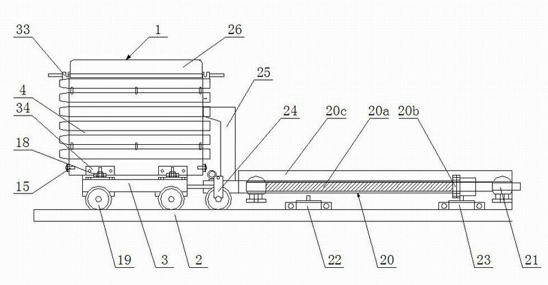
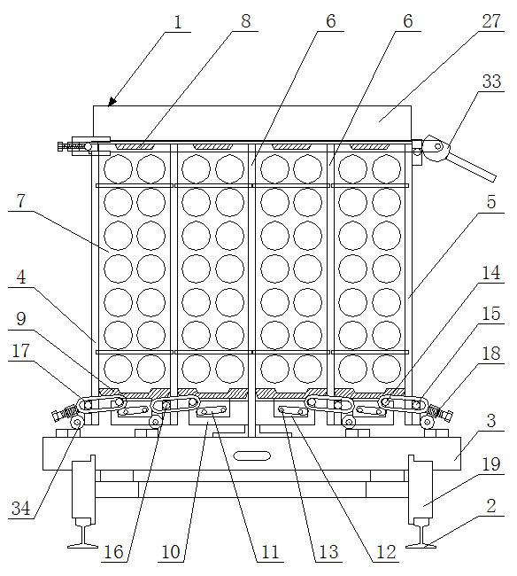
[0025] Such as figure 1 , figure 2 and image 3 As shown, the block mold box is composed of a base 3, a front formwork 4, a rear formwork 5, a partition plate 6, an end formwork 7, an upper mold 8, a bottom mold 9, a bottom module 10, a strip-shaped sliding guide hole 11, and a sliding block 12. Sliding pin 13, bottom mold pin 14, side template pin 15, middle template pin 16, pull ring 17, adjusting screw 18, running wheel 19, etc. The lower surface of the base 3 of the block mold box 1 is provided with a running wheel 19, which is erected on the track 2, and the base 3 is provided with a front side formwork 4 and a rear side formwork 5 parallel to each other. The upper ends of the side formwork 4 and the rear side formwork 5 are locked by a locking device 33. The locking device 33 is a prior art, and reference can be made to the patent "Multifunctional Gypsum Block Mold" (patent No. 200810069558.X), which The lower ends of the front template 4 and the rear template 5 are ...
Embodiment 2
[0031] Embodiment 2: In this embodiment, the bottom module 10 is fixed on both ends of the lower part of the partition plate 6, and a strip-shaped sliding guide hole 11 is opened on the bottom module 10, and the strip-shaped sliding guide hole 11 is located at the same The two bottom modules 10 are on opposite sides of the partition 6 . The bottom of the bottom mold 9 is fixed with a sliding block 12, the sliding block 12 is located between the two bottom modules 10, the sliding block 12 is provided with sliding pins 13, preferably four in the present invention, the described Four slide pins 13 are arranged in pairs on two opposite surfaces of the slide block 12, one end of the slide pin 13 is fixedly connected with the slide block 12, and the other end of the slide pin 13 extends into the opposite bottom module 10 11 in the strip-shaped sliding guide hole on the top, so that the bottom mold 9 is supported on the base 3 by the slide pin 13; the bottom mold pin 14 is also arran...
PUM
 Abstract
Description
Claims
Application Information
 - R&D
- Intellectual Property
- Life Sciences
- Materials
- Tech Scout
- Unparalleled Data Quality
- Higher Quality Content
- 60% Fewer Hallucinations
Browse by: Latest US Patents, China's latest patents, Technical Efficacy Thesaurus, Application Domain, Technology Topic, Popular Technical Reports.
© 2025 PatSnap. All rights reserved.Legal|Privacy policy|Modern Slavery Act Transparency Statement|Sitemap|About US| Contact US: help@patsnap.com


