Variable-speed moving mechanism of rack of coiling machine

A technology of moving mechanism and spring machine, which is used in the manufacture of springs, mechanical equipment, transmission devices, etc. from wires, can solve the problems of uncertain wire feeding speed, less effective wire feeding time, low production efficiency, etc., and achieves a large proportion of working time. , The effect of high spring winding precision and high production efficiency

Inactive Publication Date: 2012-07-04
SHAOXING JIADU SPRING MACHINE
View PDF8 Cites 4 Cited by
  • Summary
  • Abstract
  • Description
  • Claims
  • Application Information

AI Technical Summary

Problems solved by technology

Moreover, at the moment of starting and stopping, the steel wire will slip to an uncertain degree in the groove of the wire feeding wheel, which will affect the winding accuracy of the spring
When the clamping force of the wire feeding wheel on the steel wire is large, the steel wire will pull scratches on the groove of the wire feeding wheel, which will affect the out-of-roundness of the groove and cause the subsequent wire feeding speed to be uncertain
[0004] The cutting process of the steel wire only takes a few tenths of a second. When the height of the spring is not large, that is, when the length of wire feeding required for each spring is short, the winding process only takes a few seconds. Too frequent stops and Start-up process, resulting in short life of parts
Moreover, it also affects the production efficiency of the spring machine, so that it cannot take advantage of the maximum advantage of automated production.
[0005] The newly manufactured high-end spring machine also has a wire-feeding mechanism that uses sector gears and roller-type overrunning clutches. The disadvantages of this structure are that the effective wire feeding time is less, the production efficiency is low, and the life of the overrunning clutch is short.

Method used


Image

  • Variable-speed moving mechanism of rack of coiling machine
  • Variable-speed moving mechanism of rack of coiling machine
  • Variable-speed moving mechanism of rack of coiling machine

Examples


Embodiment 1

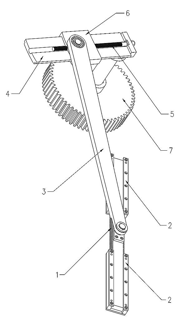
[0030] The structure of the present invention is as Figure 1 to Figure 4 As shown, it mainly includes a rack 1, a sliding seat 2, a connecting rod 3, a screw seat 4, a screw 5, a slider nut 6, and a gear 7.

[0031] The left side of the rack 1 meshes with the two clutch gears of the wire feeding wheel transmission 8, and the rotating shaft in the middle of the rack 1 is connected with the pin shaft at one end of the connecting rod 3 through a bearing; the rack 1 is slidably connected in the two sliding seats 2 , the slider 2 is fixed on the frame;

[0032] The other end of the connecting rod 3 is pinned to the slider nut 6;

[0033] The gear 7 is fixed on the frame through bearings, the gear 7 and the screw base 4 are fixed at both ends of the same rotating shaft; the screw 5 is connected to the screw base 4 through the bearing, and the slider nut 6 is connected to the screw base by sliding tenon 4, the slider nut 6 is threadedly connected with the screw mandrel 5, and when...

Embodiment 2

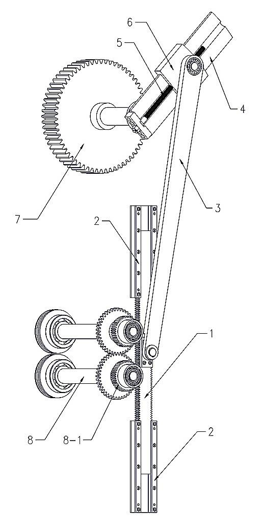
[0040] see Figure 5 , the basic structure of this embodiment is the same as that of Embodiment 1, only the rack 1 is installed horizontally, and the wire feeding in the vertical direction can be realized.

Embodiment 3

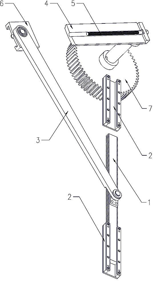
[0042] see Figure 6 , the basic structure of this embodiment is the same as that of Embodiment 1, the rack 1 has teeth on both sides, only a pair of wire feeding wheel transmissions are added on the other side of the rack, but the clutch direction of the overrunning clutch is opposite, that is, overrunning The clutch direction of the clutch should meet the following principles: the clutch directions of the diagonal clutches are consistent. Make wire feeding more powerful and reliable, suitable for conveying thick steel wire.


PUM


Abstract

A variable-speed moving mechanism of a rack of a coiling machine comprises a rack, slide seats, a connecting rod, a lead screw holder, a lead screw, a nut slider and a gear. The rack meshes with a clutch gear of a wire feeding wheel transmission device, the middle of the rack is connected with one end of the connecting rod through a pin, the rack is slidably connected between the two slide seats, and the slide seats are fixed on a framework. The other end of the connecting rod is connected to the nut slider through a pin. The gear is fixed on the framework through a bearing, and the gear and the lead screw holder are fixed on the same rotary shaft. The lead screw is connected to the lead screw holder through a bearing, the nut slider is connected to the lead screw holder through a slide tenon and is connected with the lead screw in a threaded manner, and the lead screw rotates to drive the nut slider to slide on the lead screw holder. The variable-speed moving mechanism has the advantages that a wire feeding wheel is driven to be subjected to variable-speed rotation by the rack, the acceleration and the speed of the wire feeding wheel are zero at the moment of starting and the moment of stopping, steel wires can be conveyed continuously without impaction, and accordingly the proportion of effective work time is high and production efficiency is high.

Description

technical field [0001] The invention relates to a non-cutting metal wire forming machine, in particular to a gear rack variable speed moving mechanism of a spring machine, which is suitable for [0002] The transmission device of the wire feeding wheel of the spring machine. Background technique [0003] The wire feeding transmission mechanism is a key component that every wire spring winding machine must have. There are annular grooves on the outer circle of the paired wire feeding wheel. During the spring winding process of the mechanical spring machine, the wire feeding wheel rotates at a constant speed in the opposite direction. , the steel wire is clamped in the groove of one or several pairs of wire feeding wheels and is forced to be sent out, and moves in the direction of the winding system. Resist and push the steel wire in the direction, change the forward direction of the steel wire, and make the steel wire wind up into a spring. After the spring is coiled, stop t...

Claims


Application Information

Patent Timeline
Patent Type & Authority Applications(China)
IPC IPC(8): B21F35/00B21F23/00F16H37/12
Inventor 俞家淼俞家林黄花丽俞毓彪
Owner SHAOXING JIADU SPRING MACHINE
Why Eureka
Try Eureka