Air filter device and electronic device

An air filter device and electronic equipment technology, applied in the field of electronic equipment and air filter device, can solve the problems of non-implementation, increased friction between a rotating brush and an air filter, and difficulty in smooth movement of the rotating brush, so as to achieve smooth relative movement. Effect

Inactive Publication Date: 2012-07-04
SANYO ELECTRIC CO LTD
View PDF7 Cites 3 Cited by
  • Summary
  • Abstract
  • Description
  • Claims
  • Application Information

AI Technical Summary

Problems solved by technology

[0010] However, in the device of Patent Document 1, when the rotating brush is stopped while biting into the surface of the air filter, and then the rotating brush is driven, there is a problem that the frictional force between the rotating brush and the air filter becomes large.
In addition, when the rotating brush is turned to return to the original position after moving from the standby position to the end on the opposite side, if the rotating brush is turned while biting into the surface of the air filter, there will be a gap between the rotating brush and the air. The problem of increased friction between filters
However, in this patent document 1, no countermeasure is implemented so that the rotating brush does not stop or turn around while biting into the surface of the air filter.
Therefore, in Patent Document 1, it may be difficult to smoothly move the rotating brush, and there is room for improvement.
[0011] On the other hand, in Patent Document 2, there is also the same problem as in the case of Patent Document 1
That is, when the front end portion of the bristle member of the fixed brush stops under the state of biting into the surface of the pre-filter, there is a problem that the frictional force between the fixed brush and the pre-filter becomes large when the movement of the pre-filter is started thereafter.
In addition, when the moving direction of the pre-filter is reversed, when the front end of the bristle member of the fixed brush bites into the surface of the pre-filter, there is a problem that the frictional force between the fixed brush and the pre-filter becomes large.
However, in Patent Document 2, no countermeasures are implemented for such a problem
Therefore, also in Patent Document 2, there is a problem that it may be difficult to move the rotating brush smoothly, and there is room for improvement in this regard.

Method used


Image

  • Air filter device and electronic device
  • Air filter device and electronic device
  • Air filter device and electronic device

Examples


Embodiment approach 1

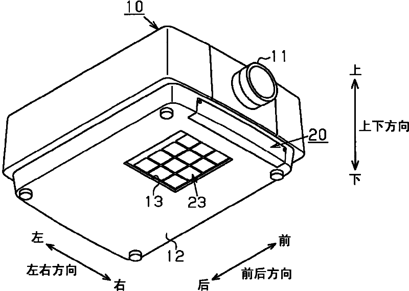
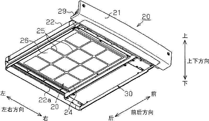
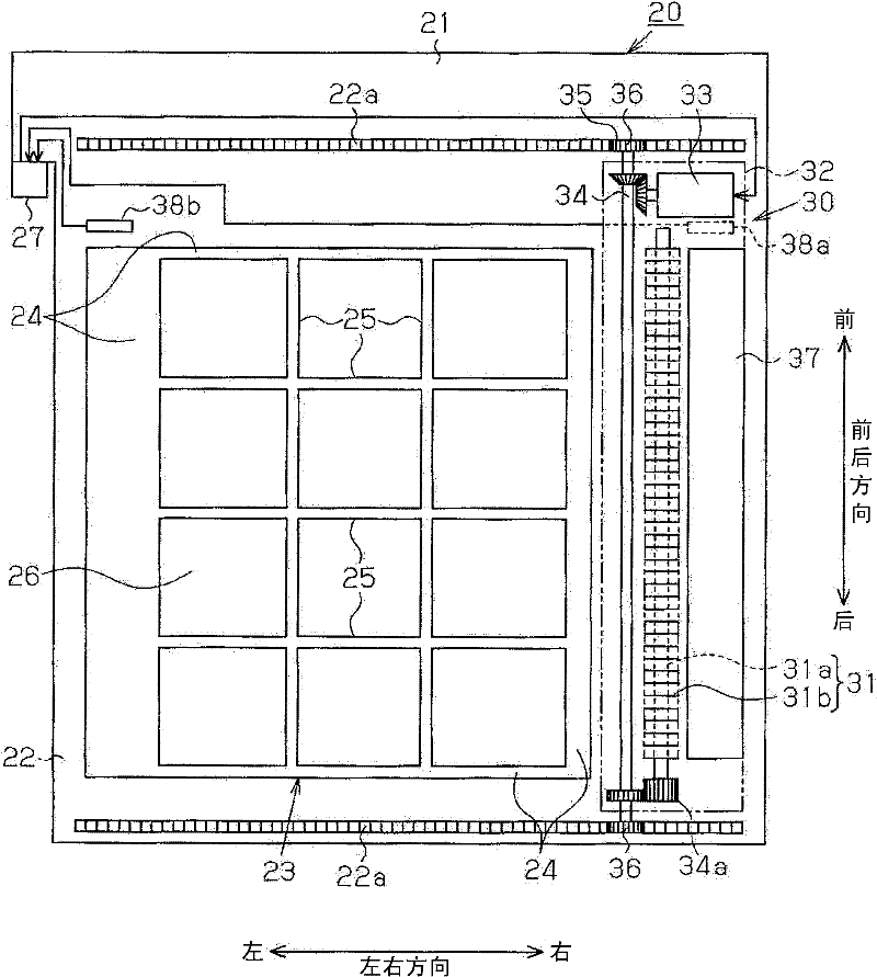
[0048] Below, refer to Figure 1 to Figure 6 The projection type video display device according to Embodiment 1 of the present invention will be described.

[0049] The projection type image display device according to this embodiment is a three-panel liquid crystal projection type image display device, which includes figure 1 A box-shaped frame body 10 as shown in the external perspective view of . It should be noted that, in the following description, the direction in which the projection-type image display device projects image light from the projection lens 11 is referred to as the front in the front-rear direction. In addition, when the projection-type video display device is installed on a horizontal plane, the direction parallel to the horizontal plane and perpendicular to the front-rear direction is defined as the left-right direction. In addition, the above-mentioned front-back direction, left-right direction, and up-down direction are indicated by arrows in each fi...

Embodiment approach 2

[0100] Next, according to Figure 7 A projection type video display device as an electronic device in Embodiment 2 will be described. In addition, about the same requirement as Embodiment 1, the same code|symbol is attached|subjected to the part described in drawing. In addition, when the components not shown in the second embodiment are described using the same reference numerals as those in the first embodiment, members assigned the same reference numerals are the same as those in the first embodiment.

[0101] On the basis of Embodiment 1, Embodiment 2 changes the configuration of the "mechanism for reducing or eliminating the biting of the brush into the air filter" of the present invention when the brush and the air filter move and reverse relative to each other.

[0102] In this embodiment, on the turned position of the left end of the air filter 23, the air filter 23 is reduced in such a way that the rotating brush 31 does not come into contact with the air filter 23 o...

Embodiment approach 3

[0108] Next, according to Figure 8 A projection type image display device as an electronic device according to Embodiment 3 will be described. In addition, about the same requirement as Embodiment 1, the same code|symbol is attached|subjected to the part described in drawing. In addition, when the components not shown in the third embodiment are described using the same reference numerals as those in the first embodiment, members assigned the same reference numerals are the same as those in the first embodiment.

[0109] On the basis of Embodiment 1 of the present invention, Embodiment 3 changes the configuration of "the mechanism for reducing or eliminating the biting of the brush into the air filter when the brush and the air filter are moved and reversed relative to each other". That is, in Embodiment 3, at the turning position of the left end of the air filter 23 , the distance between the rotating brush 31 and the air filter surface in the direction perpendicular to the...


PUM


Abstract

The present invention relates to an air filter device for smoothly performing the relative movement between a brush with distal parts of bristles of the brush penetrating an air filter surface and the air filter, and an electronic device using the air filter device. The air filter comprises: an air filter that removes dust from air drawn into a device, a slim brush, such as a rotary brush, wherein the brush removes dust from the air filter, and the brush and the air filter are relatively moved in a direction orthogonal to a longitudinal direction of the brush while distal parts of the bristles of the brush penetrate the air filter surface to remove dust from the air filter; and a unit for reducing or eliminating penetration that reduces or eliminates penetration of the brush into the air filter when relative movement of the brush and the air filter is stopped.

Description

technical field [0001] The present invention relates to an air filter device provided with a removing device for removing dust from an air filter using a brush, and an electronic device provided with the air filter device. Background technique [0002] Conventionally, in electronic equipment such as a personal computer and a projection type image display device, a method is used in which outside air is sucked in and blown as cooling air in order to cool components. In particular, in projection-type image display devices, since a light source lamp used as a light source becomes high temperature, various optical system devices typified by the light source lamp are cooled by cooling air. [0003] Also, in such electronic equipment, an air filter is used in order to capture dust in the inhaled outside air. However, if the air filter catches and accumulates dust over time, the air filter becomes clogged, the amount of intake air decreases, and the cooling effect decreases. Ther...

Claims


Application Information

Patent Timeline
Patent Type & Authority Applications(China)
IPC IPC(8): B01D46/42G03B21/14
CPCB01D46/0065B01D46/10G03B21/16B01D46/681
Inventor 西畑阳介宫永明有冈庆治小谷和范
Owner SANYO ELECTRIC CO LTD
Why Eureka
Try Eureka