


Quick Research
Generate reliable direction feasibility study reports for your R&D in just a few steps.

Technical Q&A
Discover and master advanced knowledge NOW. Basics, ideas, possibilities, all at once.

Find Solutions
As an expert in R&D theories, this can generate solutions to your technical problems instantly.

Evaluate Feasibility
Analyze your overall solution with one click, know your potential R&D risks in advance.

Monitor Landscape
Get weekly tech updates, stay abreast of the latest tech innovations and key insights.
Blasting method based on joint control of hole inside energy accumulation blasting and smooth blasting
A technology of smooth blasting and joint control, applied in blasting and other directions, can solve problems such as inability to adapt to retained rock mass, and achieve the effect of reducing support workload, improving project quality, and reducing project costs
- Summary
- Abstract
- Description
- Claims
- Application Information
AI Technical Summary
Problems solved by technology
Method used
Image

Examples
Embodiment 1
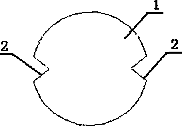
[0034] The combined control blasting method of cohesive energy blasting and smooth surface blasting in embodiment 1 (see Figure 1~2 , Figure 4~6 ), including the following steps:
[0035] (1) Delineate the peripheral contour line of the blasting excavation area according to the design requirements of the differential blasting, and arrange the differential blasting holes in the main blasting excavation area 7 .
[0036] (2) Arrange smooth blasting holes 10 along the peripheral contour of the blasting excavation area.
[0037] Wherein: the diameter of the smooth blast hole 10 is 38-42 mm.
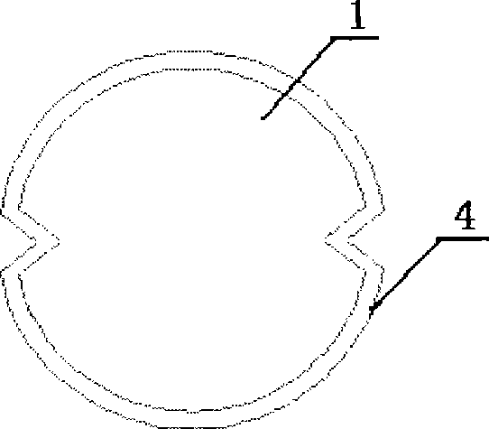
[0038] (3) Reserve the smooth surface layer 8 within the contour line of the blasting excavation area and arrange energy-concentrating blast holes 5 in the holes on the side of the main blasting excavation area 7; the thickness of the reserved smooth surface layer 8 is: blasting excavation The distance between the retained rock mass wall 9 to be formed around the area and the plane forme...
Embodiment 2
[0049] The combined control blasting method of cohesive energy blasting and smooth surface blasting in embodiment 2 (see Figure 1~2 , Figure 4~6 ), including the following steps:
[0050] (1) Delineate the peripheral contour line of the blasting excavation area according to the design requirements of the differential blasting, and arrange the differential blasting holes in the main blasting excavation area 7 .
[0051] (2) Arrange smooth blasting holes 10 along the peripheral contour of the blasting excavation area.
[0052] Wherein: the diameter of the smooth blast hole 10 is 38-42 mm.
[0053] (3) Reserve the smooth surface layer 8 within the contour line of the blasting excavation area and arrange energy-concentrating blast holes 5 in the holes on the side of the main blasting excavation area 7; the thickness of the reserved smooth surface layer 8 is: blasting excavation The distance between the retained rock mass wall 9 to be formed around the area and the plane forme...
Embodiment 3
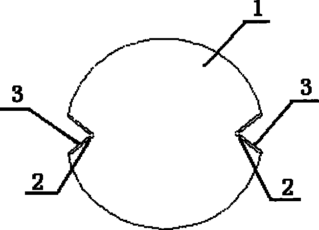
[0064] The combined control blasting method of cohesive energy blasting and smooth surface blasting in embodiment 3 (see figure 1 , Figure 3-6 ), including the following steps:
[0065] (1) Delineate the peripheral contour line of the blasting excavation area according to the design requirements of the differential blasting, and arrange the differential blasting holes in the main blasting excavation area 7 .
[0066] (2) Arrange smooth blasting holes 10 along the peripheral contour of the blasting excavation area.
[0067] Wherein: the diameter of the smooth blast hole 10 is 38-42 mm.
[0068] (3) Reserve the smooth surface layer 8 within the contour line of the blasting excavation area and arrange energy-concentrating blast holes 5 in the holes on the side of the main blasting excavation area 7; the thickness of the reserved smooth surface layer 8 is: blasting excavation The distance between the retained rock mass wall 9 to be formed around the area and the plane formed b...
PUM
 Abstract
Description
Claims
Application Information
 - R&D Engineer
- R&D Manager
- IP Professional
- Industry Leading Data Capabilities
- Powerful AI technology
- Patent DNA Extraction
Browse by: Latest US Patents, China's latest patents, Technical Efficacy Thesaurus, Application Domain, Technology Topic, Popular Technical Reports.
© 2024 PatSnap. All rights reserved.Legal|Privacy policy|Modern Slavery Act Transparency Statement|Sitemap|About US| Contact US: help@patsnap.com