
Laser resistor trimming machine control device

A laser resistance trimming and control device technology, applied in resistance manufacturing, resistors, electrical components, etc., can solve problems such as slow machine operation efficiency, unstable operation, discontinuous or paused application program operation, and improve anti-interference performance. , the effect of improving work efficiency and stability

Active Publication Date: 2012-06-20
沈玉良
View PDF3 Cites 1 Cited by
  • Summary
  • Abstract
  • Description
  • Claims
  • Application Information

AI Technical Summary

Problems solved by technology

Due to the dynamic changes of system resources and the automation of system program settings (such as the execution of automatic backup programs, etc.), often when executing the laser resistance trimming application program, the application program will run discontinuously or stop, causing the laser resistance trimming machine to run fast and sometimes slow ( Non-linear, especially when the system has multiple applications executing, the machine operation efficiency is exceptionally slow and unstable)

Method used


Image

  • Laser resistor trimming machine control device
  • Laser resistor trimming machine control device
  • Laser resistor trimming machine control device

Examples


Embodiment Construction

[0034] The following will clearly and completely describe the technical solutions in the embodiments of the present invention with reference to the accompanying drawings in the embodiments of the present invention. Obviously, the described embodiments are only some, not all, embodiments of the present invention. Based on the embodiments of the present invention, all other embodiments obtained by persons of ordinary skill in the art without making creative efforts belong to the protection scope of the present invention.

[0035] In order to make the above objects, features and advantages of the present invention more comprehensible, the present invention will be further described in detail below in conjunction with the accompanying drawings and specific embodiments.

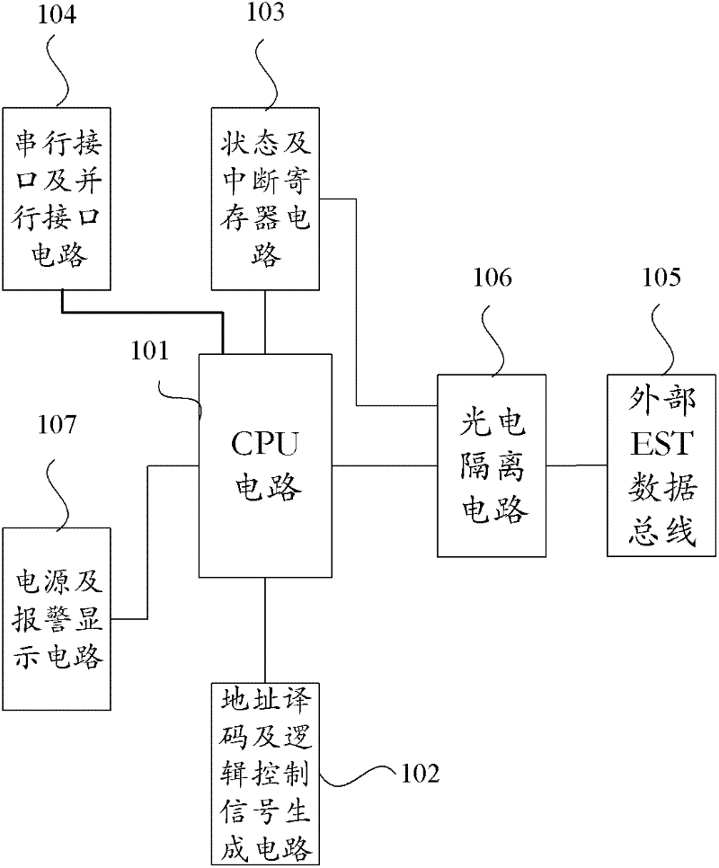
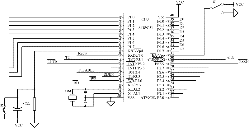
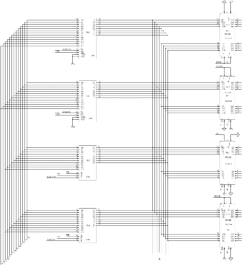
[0036] figure 1 It is a structural diagram of the control device of the laser resistance trimming machine disclosed in the present invention. like figure 1 As shown, the circuit includes: CPU circuit 101, addres...


PUM


Abstract

The invention discloses a laser resistor trimming machine control device which comprises a CPU circuit, an address decoding and logic control signal generation circuit, a state and interrupt register circuit, a serial interface and parallel interface circuit, and an external EST data bus; the CPU circuit is respectively connected with the address decoding and logic control signal generation circuit, the state and interrupt register circuit, and the external EST data bus; the serial interface and parallel interface circuit is connected with the CPU circuit; the state and interrupt register circuit is connected with the external EST data bus. The laser resistor trimming machine control device disclosed by the invention can control a laser resistor trimming machine through a separate hardware circuit, and operation and control can be performed without the occupation of a CPU of a PC machine; and thus the working efficiency and stability of the laser resistor trimming machine are improved.

Description

technical field [0001] The invention relates to the field of integrated circuit manufacturing equipment, in particular to a control device for a laser resistor trimming machine. Background technique [0002] Laser trimming is a process of trimming the resistance value of resistors. The principle is: when a high-power laser beam hits the surface of a thick-film or thin-film resistive material, the medium of the resistive material where the beam hits vaporizes, increasing the resistance value. The laser resistance trimming machine is a device that uses this principle to trim the resistance to obtain a resistance that meets the resistance accuracy requirements. [0003] In the prior art, when the laser resistance trimming machine is in use, the laser resistance trimming machine is connected to a PC host. The driver program of the laser resistance trimming machine and the laser resistance trimming application program are installed on the PC host. The PC host realizes the cont...

Claims


Application Information

Patent Timeline
IPC IPC(8): H01C17/242
Inventor 沈玉良
Owner 沈玉良
Learn More