Load test device for large-power frequency converter adopting front active end

A technology of load test and frequency converter, which is applied in the field of frequency converter, can solve the problems of many intermediate links, complex connection, large energy loss of mechanical parts, etc., and achieve the effect of less auxiliary equipment, simple connection and easy realization

Active Publication Date: 2012-06-20
TIANJIN RES INST OF ELECTRIC SCI +1
View PDF4 Cites 9 Cited by
  • Summary
  • Abstract
  • Description
  • Claims
  • Application Information

AI Technical Summary

Problems solved by technology

[0003] In order to ensure the reliability of high-power inverter equipment, it is necessary to test its components or the whole during its design, development and production process. When the inverter has a large capacity, it is very difficult to test the large-capacity inverter
Common inverter load test methods include: single slip motor stall method, asynchronous motor slip pair drag method, AC unit pair drag method and AC / DC unit pair drag method, etc., to adopt these methods, it is necessary to provide power matching The motor and the corresponding controller constitute a load unit, which is very inconvenient to install and debug, and has high requirements for the test site and power supply capacity
Although the above methods can realize the power feedback of the frequency converter to be tested, due to the many intermediate links and complicated connections, the energy loss of mechanical parts is also relatively large. The power grid takes more power

Method used


Image

  • Load test device for large-power frequency converter adopting front active end
  • Load test device for large-power frequency converter adopting front active end
  • Load test device for large-power frequency converter adopting front active end

Examples


Embodiment Construction

[0021] Embodiments of the present invention are described in further detail below in conjunction with the accompanying drawings:

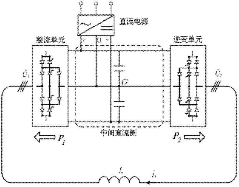
[0022] A high-power inverter load test device adopting an active front end realizes the load performance test function of the AC-DC-AC structure high-power inverter. The voltage and power factor output by the frequency converter are flexible and adjustable, and can simulate the working conditions of the load motor in four quadrants. The topology of the frequency converter to be tested can be a two-level or multi-level structure, and the power device used in the frequency converter can be IGCT or IGBT. Such as figure 1 As shown, the high-power inverter load test device using the active front end includes an inverter, a DC power supply and a reactor. In this embodiment, the inverter is a three-level midpoint voltage clamping structure. , the intermediate DC side, and the inverter unit. A reactor with a small capacity is connected between the rectif...


PUM


Abstract

The invention relates to a load test device for a large-power frequency converter adopting a front active end. The main technical characteristics are that: the load test device comprises a frequency convertor, a reactor and a direct-current power supply; the reactor is connected between a rectification unit and an inversion unit of the frequency convertor; the front active end is adopted by the rectification unit; and the direct-current power supply is connected with the middle direct-current side of the frequency convertor to ensure that the rectification unit, the middle direct current side, the inversion unit, and the reactor form a power loop. The load test device has reasonable design, and can be implemented by only one reactor with small capacity, and an externally connected power supply with small capacity; and other power consumption except loss on a power device and a line is avoided in the whole test process, and large-power current can pass through the frequency convertor only taking a small amount of energy from a power grid, so that the function that a power grid with small capacity is subjected to load test of the large-power frequency converter can be realized, and the load test device has the advantages of simple structure, accurate test result, few auxiliary appliance and the like and is easy to implement.

Description

technical field [0001] The invention belongs to the field of frequency converters, in particular to a high-power frequency converter load test device using an active front end. Background technique [0002] Frequency conversion speed regulation technology has become an important means to save energy and reduce consumption, improve process flow, improve product quality and environment, and promote technological progress in the industrial field. In recent years, with the continuous emergence of high-power power electronic devices, the single-unit capacity of frequency converters has increased rapidly, and various megawatt-level frequency converters have been widely used in large-scale industrial production equipment. [0003] In order to ensure the reliability of high-power inverter equipment, it is necessary to test its components or the whole during its design, development and production process. When the inverter has a large capacity, it is very difficult to test the large-...

Claims


Application Information

Patent Timeline
Patent Type & Authority Applications(China)
IPC IPC(8): G01R31/00
Inventor 宋鹏伍丰林金雪峰许希楚子林
Owner TIANJIN RES INST OF ELECTRIC SCI
Why Eureka
Try Eureka