
System for securing a rail and securing a rail

A technology of fixing device and track, applied in the field of system for fixing track and track fixing device, can solve problems such as loosening of fixing screws, and achieve the effect of convenient number of components and low cost

Inactive Publication Date: 2012-06-13
VOSSLOH WERKE GMBH
View PDF8 Cites 2 Cited by
  • Summary
  • Abstract
  • Description
  • Claims
  • Application Information

AI Technical Summary

Problems solved by technology

[0006] In practice, a problem with track fixtures of the type described above is that the fixing screws can loosen, necessitating maintenance repairs to the fixture after a relatively short application time

Method used


Image

  • System for securing a rail and securing a rail
  • System for securing a rail and securing a rail
  • System for securing a rail and securing a rail

Examples


Embodiment Construction

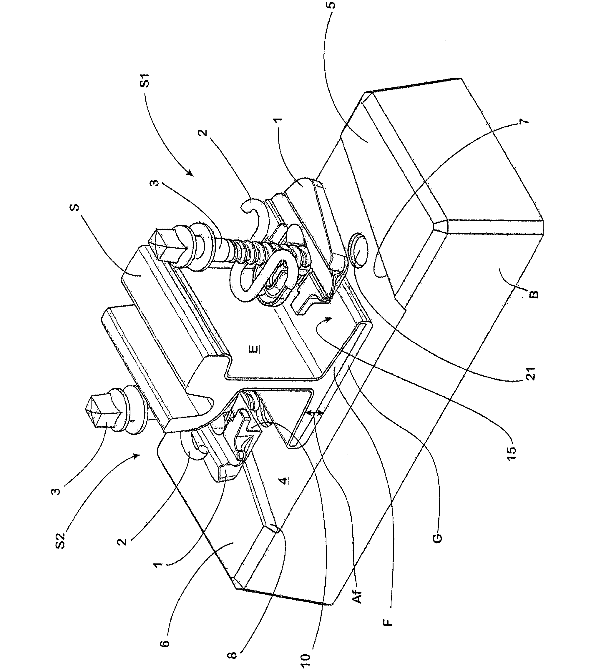
[0085] In order to fix the track S formed as a grooved track on the fixed base formed by the concrete sleeper B, it is realized by using two systems S1, S2 formed in this way, which respectively comprise the guide plate 1, the spring part 2 and the Clamping screw 3 for tight parts.

[0086] A planar ground contact surface 4 is formed in the concrete sleeper B, the long sides of which abut against the long sides of the sleeper B, while the wide sides of the contact surface are each delimited by a shoulder 5 , 6 . The supporting surfaces 7 , 8 of the shoulders 5 , 6 , which correspond to the contact surface 4 and run parallel to each other, are arranged at acute angles to the long sides of the contact surface 4 , so that the contact surface 4 has a parallelogram shape in plan view.

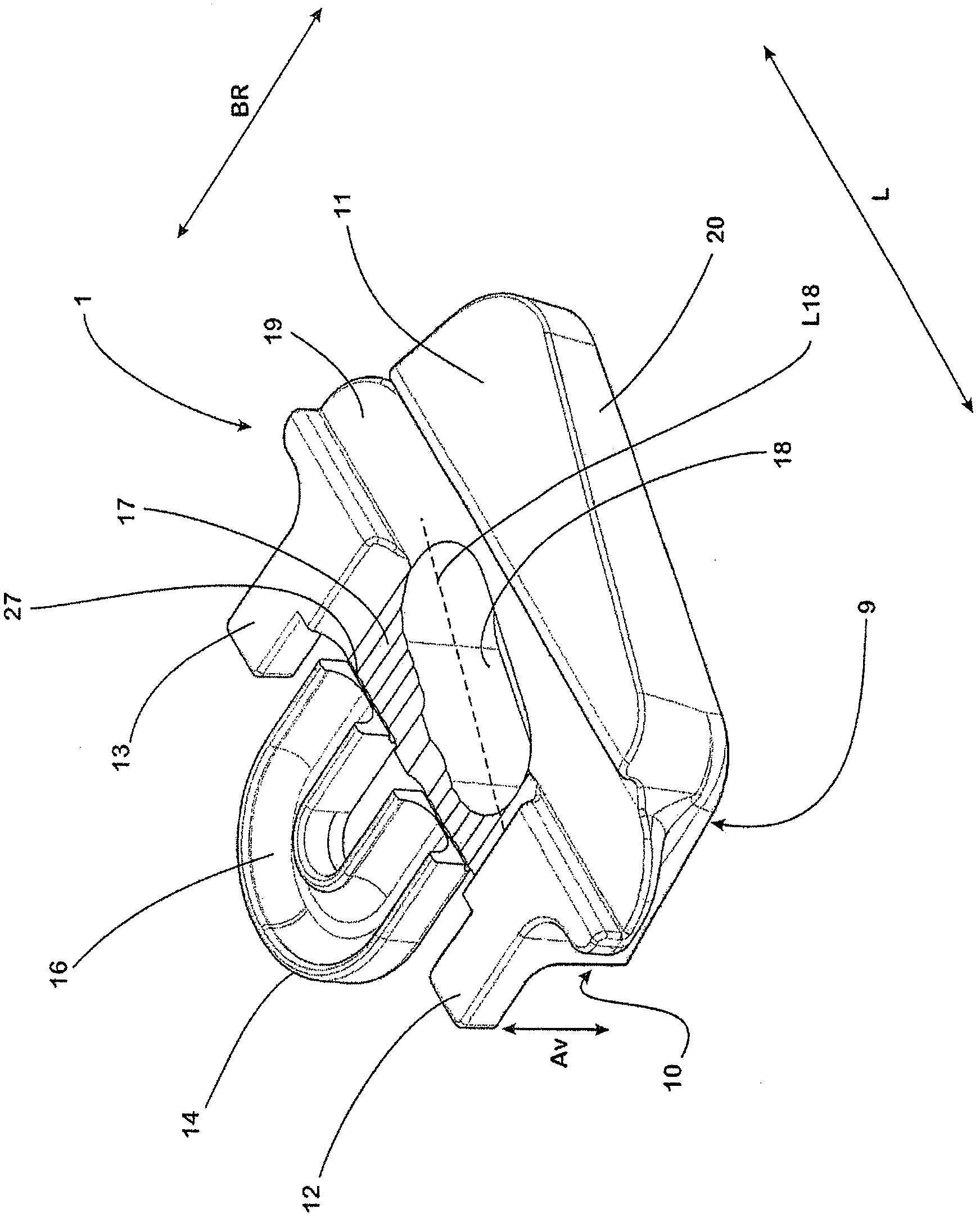
[0087] The guide plates 1 are made of non-conductive, for example fiber-reinforced plastic, and each have a support surface 9 on their undersides, with which the guide plates rest on the contact sur...


PUM


Abstract

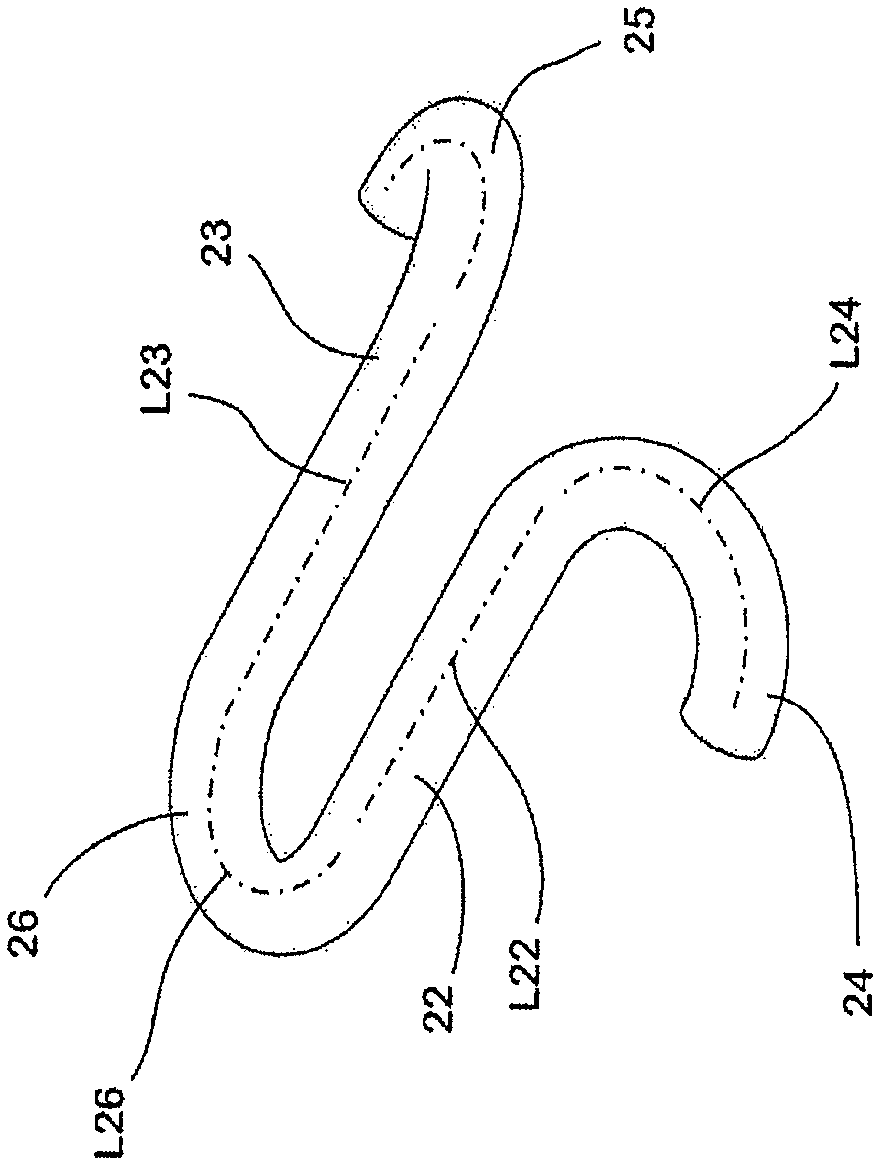
The invention relates to a system (S1, S2) for securing a rail (S) to a solid foundation (B), comprising a guide plate (1,30), a securing element (3) and a spring element (2). Said guide plate (1,30) comprises a bearing surface (10) on which the longitudinal side of the rail base (F) rests when in the mounted position. Said spring element (2) has a W or S shaped frame and comprises a section (22, 23, 26) which, when in the mounted state, protrudes so far over the rail base (F) that said rail base (F) is maintained elastically by said spring element (2) when it moves upwards, away from the solid foundation (B) in the vertical direction.

Description

technical field [0001] The invention relates to a system for fixing a rail on a foundation and a fixing device for a rail using this system. Background technique [0002] In the fastening of rails that are subject to low loads and speeds when vehicles are running over them, such as in the case of trams, it is important to have as little wear as possible on the one hand and to have as little wear as possible on the other On the one hand, it must have driving comfort and minimize noise pollution. At the same time, such a fastening device should be easy to assemble and inexpensive to produce. [0003] In the rail fastenings used in practice, the above-mentioned requirements are fulfilled by fitting the rails to fixed, for example concrete sleepers or to a foundation formed by a single support point made of concrete, wherein between the rail foot and the fixed An elastic layer is provided between the bases, and the elastic layer has limited elasticity. In this case, the elast...

Claims


Application Information

Patent Timeline
Patent Type & Authority Applications(China)
IPC IPC(8): E01B9/30
CPCE01B9/66E01B9/303
Inventor 温弗里德·博斯特林卢茨·拉德马赫阿德里安·贝德纳尔奇克
Owner VOSSLOH WERKE GMBH
Learn More