
Power factor correction circuit for reducing harmonic distortion of LED (light-emitting diode) drive circuit

A technology of power factor correction and harmonic distortion, which is applied in electric lamp circuit layout, high-efficiency power electronic conversion, and output power conversion devices, etc., can solve the problems of LED lamp efficiency, cost, increased volume and weight, and expensive LED lamp.

Inactive Publication Date: 2012-06-13
NORTH CHINA UNIVERSITY OF TECHNOLOGY
View PDF2 Cites 12 Cited by
  • Summary
  • Abstract
  • Description
  • Claims
  • Application Information

AI Technical Summary

Problems solved by technology

If there are a large number of harmonics in the input current, the level of harmonic noise will increase. At the same time, a filter is added to the input end of the AC-DC rectifier circuit, which will increase the cost and volume weight; a large number of harmonic components will flow back into the power grid, causing damage to the power grid. Harmonic pollution produces secondary effects, so its power factor correction has a major impact on the efficiency of LED lamps
However, in order to reduce the price of LELD lighting, many manufacturers omit PFC or make LED lights more expensive even though they have PFC circuits, which is not good for the development prospects of LED lights. important direction

Method used

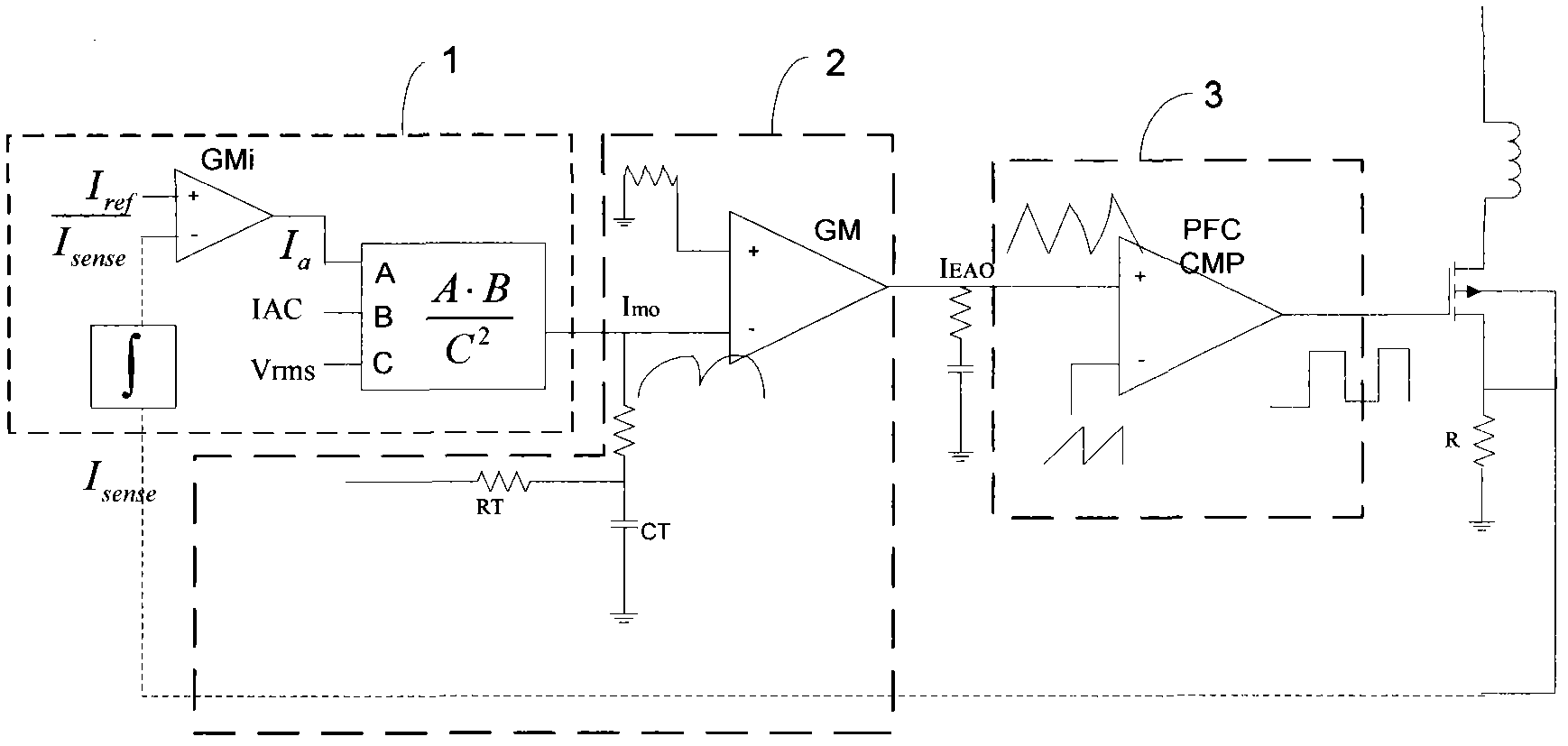
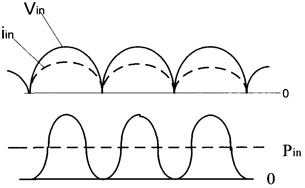

Image

  • Power factor correction circuit for reducing harmonic distortion of LED (light-emitting diode) drive circuit
  • Power factor correction circuit for reducing harmonic distortion of LED (light-emitting diode) drive circuit
  • Power factor correction circuit for reducing harmonic distortion of LED (light-emitting diode) drive circuit

Examples


Embodiment Construction

[0019] Power factor refers to the relationship between effective power and total power consumption (apparent power), that is, the ratio of effective power divided by total power consumption (apparent power). Basically, the power factor can measure the degree to which electricity is effectively utilized. When the value of the power factor is larger, it means that the power utilization rate is higher.

[0020] Definition of power factor:

[0021] PF=P / VI (1)

[0022] Assuming that the input voltage Vi (effective value V) of the AC-DC converter circuit is sinusoidal and the input current is non-sinusoidal, its effective value is

[0023] I = I 1 2 + I 2 2 + I 3 2 + · ...


PUM


Abstract

The invention relates to a power factor correction circuit for reducing the harmonic distortion of an LED (light-emitting diode) drive circuit, which adopts an average current mode in a CCM (continuous conduction mode). The circuit comprises a multiplier, an operational amplifier and a PFC (power factor correction) comparison amplifier, wherein the circuit adopts a corrected input current (Isense), and a signal obtained after the input current (Isense) is changed with an input voltage is taken as an input end of the multiplier; a current value obtained by virtue of a resistor after a line voltage (IAC) of an alternating voltage of the circuit is rectified is taken as another input end of the multiplier; and an average value (Vrms) end of the input voltage adopts a squarer, and an LED lamp is driven by using a CCM technique.

Description

technical field [0001] The invention belongs to the field of solid-state lighting sources, and more specifically relates to the field of LED lighting source circuits. Background technique [0002] With the continuous consumption of energy, the issue of energy conservation and environmental protection has become an important part of the sustainable development of today's society. Energy conservation, emission reduction, environmental protection, and the use of green energy are an important trend in social development. As the fourth-generation lighting source, LED lights have many advantages such as long life, environmental protection, low power consumption, high luminous efficiency, multi-color light, adjustable light, and can work under safe low voltage. They gradually replace fluorescent lamps, and incandescent lamps become a new generation. The direction of the lighting source. The application of LEDs has ranged from the initial indicator lights to traffic signals and lar...

Claims


Application Information

Patent Timeline
Patent Type & Authority Applications(China)
IPC IPC(8): H05B37/02H02M1/42
CPCY02B70/126Y02B70/10
Inventor 姜岩峰赵帆
Owner NORTH CHINA UNIVERSITY OF TECHNOLOGY
Learn More