Power source conversion circuit and network camera with same
A network camera and power switching technology, applied in the direction of data exchange network, data switching current source, electrical components, etc., can solve the problems of POE circuit error output, continuous restart, etc., to improve reliability, reduce construction cost, and flexible application Effect
- Summary
- Abstract
- Description
- Claims
- Application Information
AI Technical Summary
Problems solved by technology
Method used
Image
Examples
Embodiment 1
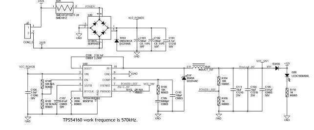
[0017] Embodiment one, with reference to Figure 1-Figure 3 , the first power supply in this embodiment is a 24V power supply, the second power supply is a POE power supply, and the POE power supply circuit refers to figure 1 , the power supply process is as follows: At the beginning, the PSE device outputs a small voltage on the port until it detects that the connection of the cable terminal is a power receiving device that supports the IEEE 802.3af standard. After detecting the power receiving device PD , the PSE device may classify the PD device and evaluate the power loss required by the PD device. The standard Category 5 network cable has four pairs of twisted pairs, but only one of them is used in l0M BASE-T and 100M BASE-T When using the free pins for power supply, the 4 and 5 pins are connected to the positive pole, and the 7 and 8 pins are connected to the negative pole. A rectifier bridge rectifies the power supply to the idle pin and the data pin respectively to en...
Embodiment 2
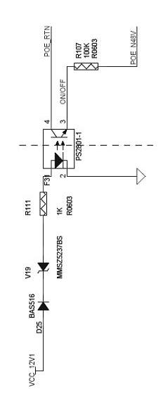
[0022] Embodiment 2. This embodiment proposes a network camera. The power switching circuit of the embodiment is installed at the front end of the power supply in the network camera to provide power input for other systems in the camera. The power switching system includes a power supply circuit connected in sequence with the 24V Diode D25, reverse diode V19 and current limiting resistor R11, diode D25, reverse diode V19 and current limiting resistor R111 form a current limiting protection circuit, the other end of the current limiting protection circuit is connected to the first input end of optocoupler PS2801-1 , the second input terminal of the optocoupler PS2801-1 is grounded, the first output terminal is connected to the enable terminal of the POE power supply, and the second output terminal is connected to the POE reference ground terminal POE_N48V through a pull-down resistor R107.
[0023] When the IP camera is running, the 24V AC power supply V1 is preferred. At this t...
PUM
 Abstract
Description
Claims
Application Information
 - R&D
- Intellectual Property
- Life Sciences
- Materials
- Tech Scout
- Unparalleled Data Quality
- Higher Quality Content
- 60% Fewer Hallucinations
Browse by: Latest US Patents, China's latest patents, Technical Efficacy Thesaurus, Application Domain, Technology Topic, Popular Technical Reports.
© 2025 PatSnap. All rights reserved.Legal|Privacy policy|Modern Slavery Act Transparency Statement|Sitemap|About US| Contact US: help@patsnap.com


