Electronic potentiometer and calibration method thereof

An electronic potentiometer and calibration method technology, which is applied in the field of sensors, can solve the problems of high uniformity of coil winding, difficult to adjust the potential level accurately, difficult linearity adjustment, etc., and achieve simple and novel calibration methods, convenient debugging, and easy Achieved effect

Inactive Publication Date: 2015-01-28
蒋勤舟
View PDF7 Cites 0 Cited by
  • Summary
  • Abstract
  • Description
  • Claims
  • Application Information

AI Technical Summary

Problems solved by technology

[0003] The Chinese patent number is 98212193.8, and the utility model patent named "inductive liquid level sensor" discloses an electromagnetic sensor with a slope-shaped iron core, which is characterized in that the displacement change is realized by changing the relative conductivity of the iron core in the coil It is mentioned in the instruction manual that: the shape of the iron core can be conical, circular, pyramid, pyramid, etc., and the linearity can be corrected by correcting the iron core, but no matter what kind of iron core is proposed in the instruction, it has a rigid structure. Strong and high cost. To correct the iron core, it can only be polished the overall slope of the iron core. As the manual says, the overall slope of the iron core is kept consistent. It is very difficult, so there is almost no such technical solution in the current electromagnetic sensors
But this utility model has the following deficiencies: the first is that although the wear problem of the potentiometer is solved, the sensor made by the principle of variable inductance has been applied in more and more fields, and its main function is to combine various physical characteristics It is converted into electrical characteristics, so as to realize the automatic detection of various parameters, but this patented technology is difficult to realize the precise adjustment of the potential level, let alone use the potentiometer to detect various parameters; the second is that the linearity is not easy to adjust, variable Inductive sensors usually use solid iron cores, which have high requirements on the uniformity of core processing and coil winding

Method used


Image

  • Electronic potentiometer and calibration method thereof
  • Electronic potentiometer and calibration method thereof
  • Electronic potentiometer and calibration method thereof

Examples


Embodiment Construction

[0033] The present invention will be described in further detail below in conjunction with the accompanying drawings and specific embodiments.

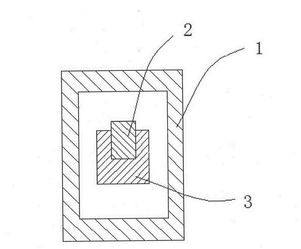
[0034] Such as figure 1 with Figure 4 As shown, an electronic potentiometer includes a coil 1, a magnetically conductive sheet 2, a support frame 3, etc., a support frame 3 is pierced in the inner cavity of the coil 1, and the magnetically conductive sheet is fixed on the support frame 3. sheet 2, the support frame 3 can drive the magnetic conductive sheet 2 to move in the inner cavity of the coil 1 .

[0035] Such as figure 2 with Figure 4As shown: the support frame 3 has a "C"-shaped structure, and a "C"-shaped magnetic guide sheet installation bar groove 3a is opened on the upper end surface of the support frame 3, and the magnetic guide sheet 2 is embedded and fixed in the guide The magnetic sheet is installed in the bar groove 3a; certainly the above-mentioned support frame 3 is not necessarily in a "C" shape structure, an...


PUM


Abstract

The invention discloses an electronic potentiometer and a calibration method thereof. A noncontact potentiometer comprises a coil and a magnetic conductive sheet. A bracing frame passes through an inner cavity of the coil; the magnetic conductive sheet is fixed on the bracing frame; the bracing frame can drive the magnetic conductive sheet to move in the inner cavity of the coil; the bracing frame is in a ''C'' shape and is provided with a ''C'' shape magnetic conductive sheet installation groove on an upper end thereof; and the magnetic conductive sheet is inserted and fixed in the magnetic conductive sheet installation groove and is a ribbon with a width changed from large to small. A calibration method of the noncontact potentiometer comprises steps of: measurement, adjustment, calibration and assembly. According to the invention, adjustment of variable inductance parameters are realized through arrangement of the bracing frame and change of a physical structure of the magnetic conductive sheet, so as to simplify processing algorithm in a subsequent circuit, easily realize detection circuit and facilitate installation and debug of a sensor. The potentiometer calibration method provided by the invention is simple and novel and has characteristics of convenience, fastness and high precision, etc.

Description

technical field [0001] The invention relates to sensor technology, specifically, an electronic potentiometer and its calibration method. Background technique [0002] The potentiometer is a resistive element with three terminals and the resistance value can be adjusted according to a certain change rule. It usually consists of a resistor body and a movable brush or sliding system. When the brush moves along the resistor body, a resistance value or voltage that has a certain relationship with the displacement is obtained at the output end. That is, when a voltage is applied between the two fixed contacts of the resistor, the position of the contact on the resistor is changed by rotating or sliding the system, and a position corresponding to the position of the movable contact can be obtained between the movable contact and the fixed contact. into a certain relationship with the voltage. The potentiometer currently used is generally an electric shock potentiometer, which is ...

Claims


Application Information

Patent Timeline
Patent Type & Authority Patents(China)
IPC IPC(8): H01C10/00H01C17/00
Inventor 蒋勤舟
Owner 蒋勤舟
Why Eureka
Try Eureka