
Measuring device of dense two-phase flow particle speed and concentration spatial distribution

A technology of particle velocity and spatial distribution, which is applied in the field of multiphase flow measurement, can solve problems such as little research and understanding of flow mechanism, unsatisfactory repeatability and reliability of measurement results, and obstacles to the enlargement and operation of fluidization equipment.

Inactive Publication Date: 2013-11-27
SOUTHEAST UNIV
View PDF4 Cites 0 Cited by
  • Summary
  • Abstract
  • Description
  • Claims
  • Application Information

AI Technical Summary

Problems solved by technology

Traditional two-phase flow measurement methods have low measurement accuracy, and the repeatability and reliability of measurement results are not ideal; modern measurement methods are widely used in the field of two-phase flow measurement due to their high spatial and temporal resolution, but the existing measurement The method has only been successfully promoted in the measurement of dilute phase flow. For example, there are PIV velocimeters on the market, but there is still no breakthrough in the measurement of dense phase, especially the measurement of particle velocity and concentration spatial distribution in the dense phase flow field. Progress
Due to the limitation of dense two-phase flow measurement technology, there is little research and understanding of the complex flow mechanism inside fluidized devices such as spouted fluidized beds, which leads to obstacles in the scale-up and application of fluidized equipment in industrial production.

Method used


Image

  • Measuring device of dense two-phase flow particle speed and concentration spatial distribution
  • Measuring device of dense two-phase flow particle speed and concentration spatial distribution
  • Measuring device of dense two-phase flow particle speed and concentration spatial distribution

Examples


Embodiment Construction

[0020] The present invention will be described below with reference to the accompanying drawings.

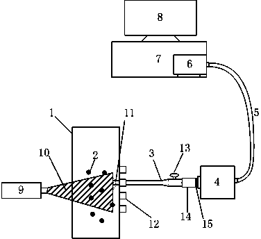
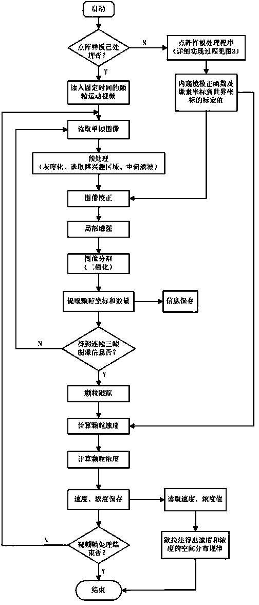
[0021] The device for measuring the spatial distribution of particle velocity and concentration in the dense two-phase flow field provided by the present invention is composed of a fiber optic endoscope, a high-speed industrial camera, an image acquisition card, a computer, and a sheet-shaped laser source. The particle motion video in the field is shot and saved, and the image processing software processes the particle motion video off-line to obtain the spatial distribution of particle velocity and concentration.

[0022] Its characteristics are: as the optical lens of the high-speed photography device, the fiber optic endoscope can go deep into the interior of the dense phase flow field to shoot the movement process of particles; Parameters such as time and resolution can obtain high-quality particle video images for different working conditions; the laser light source provide...


PUM


Abstract

The invention discloses a measuring device of dense two-phase flow particle speed and concentration spatial distribution. The invention is characterized in that: the device comprises an image acquisition terminal and an image processing unit (8); the image acquisition terminal is used for shooting a motion video of a particle (2) in a fluidization apparatus (1), and the image acquisition terminal comprises a laser source (9), a fiber endoscope (3), a high speed industrial camera (4), an image acquisition card (6) and a computer (7); a sheet-shaped laser beam (10) is provided by the laser source (9) to determine a measurement area in the fluidization apparatus (1); the fiber endoscope (3) shoots the determined measurement area as an optical lens, a lens of the fiber endoscope (3) is parallel with a plane of the laser beam (10), and a distance between the lens and the laser beam (10) is maintained at 10 mm. According to the invention, since the fiber endoscope is used as the optical lens, multi-angle measurement in a flow field is conveniently realized, and a difficulty that a motion parameter of the particle in a dense phase flow field can not be obtained is overcome.

Description

technical field [0001] The invention provides a measuring device for the velocity and concentration spatial distribution of moving particles in a dense two-phase flow field, which is especially suitable for measuring the velocity and concentration spatial distribution of dense phase particles in a gas-solid spouted bed, and belongs to the field of multiphase flow measurement . Background technique [0002] The spatial distribution of velocity and concentration of two-phase flow is the key parameter for analyzing the fluid dynamics in two-phase flow, and it is the premise for understanding the heat transfer and mass transfer mechanism between two-phase fluids in fluidization devices. Design and optimization of structural parameters are of great significance. [0003] At present, there are many methods to measure particle velocity and concentration in two-phase flow field. The traditional measurement methods include impact force method, constant velocity sampling method, heat...

Claims


Application Information

Patent Timeline
Patent Type & Authority Patents(China)
IPC IPC(8): G01M10/00G01P3/38G01N15/06
Inventor 张继彬陆勇钟文琪
Owner SOUTHEAST UNIV
Learn More