Counterpoint device of cutting machine

A technology of alignment device and cutting machine, which is applied in the field of TFT-LCD manufacturing process, can solve the problems of increased production cost, expensive porous carbon fiber material, unfavorable popularization, etc., and achieve the effect of ensuring smooth use, reducing cost, and ensuring alignment effect

Active Publication Date: 2014-04-09
TCL CHINA STAR OPTOELECTRONICS TECH CO LTD
View PDF5 Cites 0 Cited by
  • Summary
  • Abstract
  • Description
  • Claims
  • Application Information

AI Technical Summary

Problems solved by technology

However, the price of porous carbon fiber materials is too expensive, which increases production costs to a large extent and is not conducive to popularization

Method used


Image

  • Counterpoint device of cutting machine
  • Counterpoint device of cutting machine
  • Counterpoint device of cutting machine

Examples


Embodiment Construction

[0021] In order to further illustrate the technical means adopted by the present invention and its effects, the following describes in detail in conjunction with preferred embodiments of the present invention and accompanying drawings.

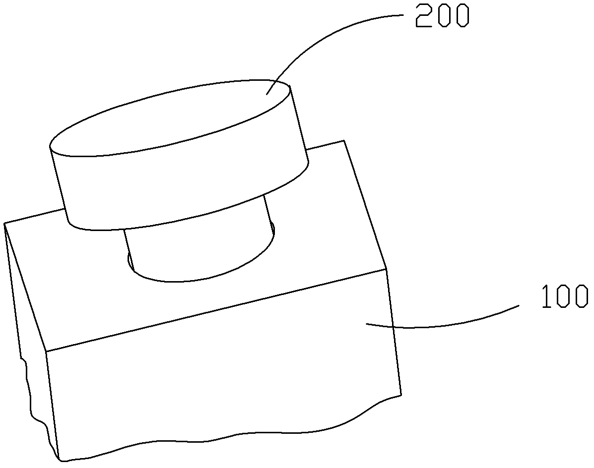
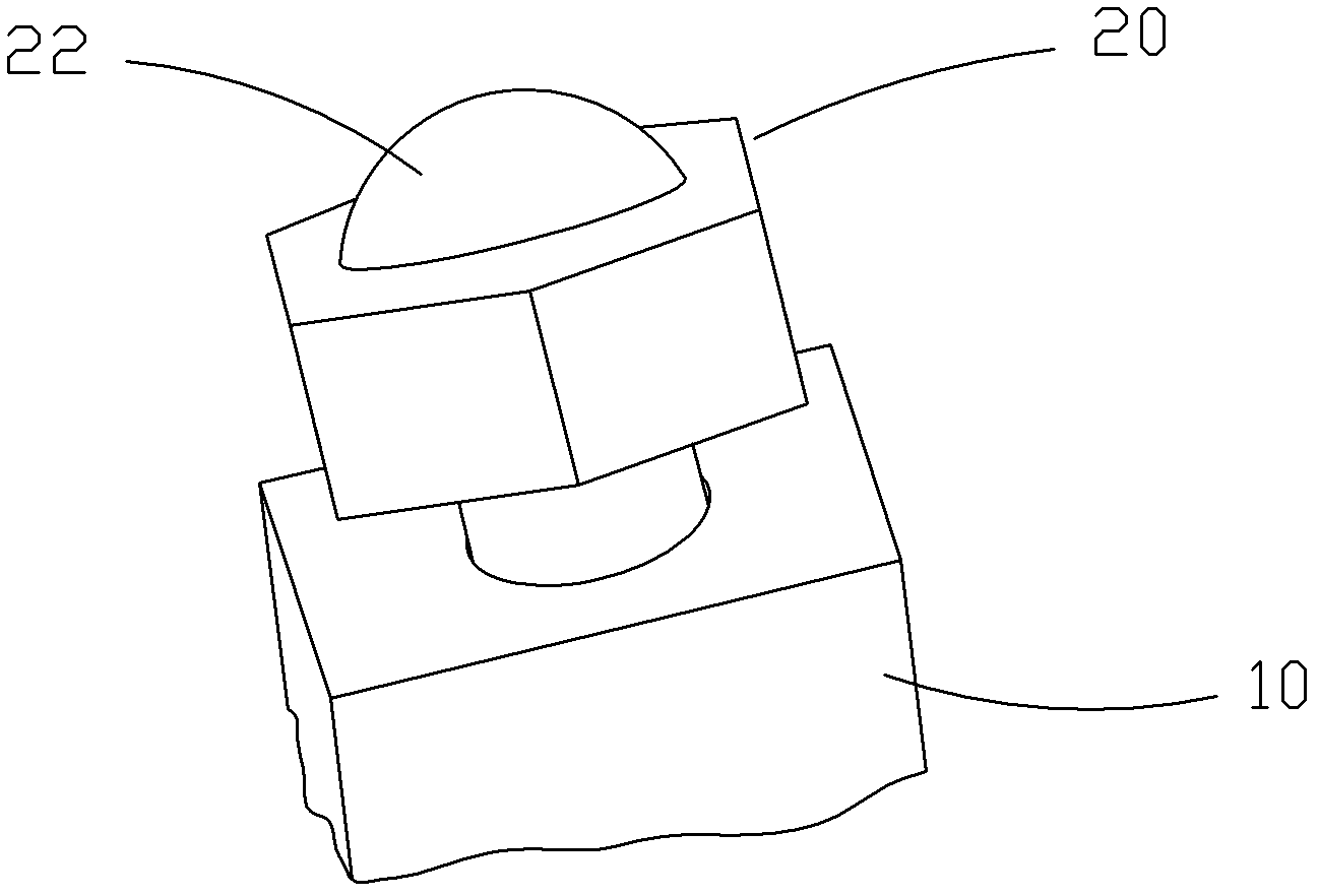
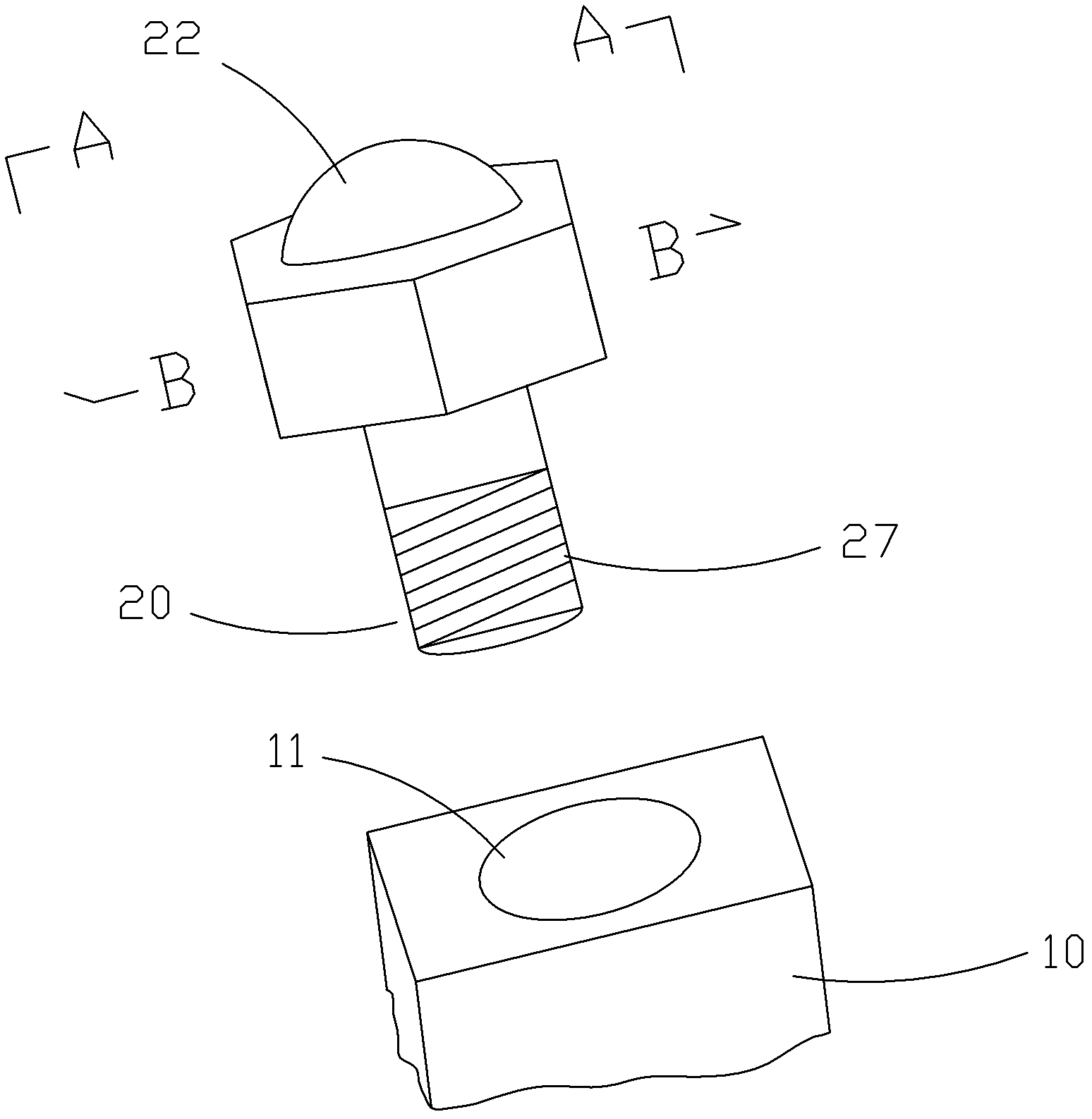
[0022] Such as Figure 2-6 As shown, the present invention provides an alignment device for a cutting machine, which includes: a mounting base 10, and a universal ball 20 installed on the mounting base. works the same way. In the present invention, the universal ball 20 is used to replace the floating pad made of porous carbon fiber material to align the glass substrate, so as to reduce the cost.

[0023] The universal ball 20 includes a main body 21, a first rolling body 22, and several second rolling bodies 23 arranged between the main body 21 and the first rolling body 22. One end of the main body 21 is provided with an accommodating groove 24 to form a The side wall 241 of the accommodation groove, the second rolling body 23 is rotatably...


PUM


Abstract

An alignment apparatus for a cutting machine, comprising: a mount base (10) and an omni-directional ball (20) mounted on the mount base (10). The omni-directional ball (20) comprises a main body (21), a first rolling body (22), and several second rolling bodies (23) provided between the main body (21) and the first rolling body (22). The main body (21) is provided at one end thereof with a receiving groove (24), thereby forming a receiving groove sidewall (241), while the other end is provided with a connector part (27) for matingly connecting to the mount base (10). The second rolling bodies (23) are rollably arranged on the receiving groove sidewall (241). The main body (21) is provided thereon with an air inlet (25) in communication with the receiving groove (24). The receiving groove sidewall (241) is provided with an abutment part (26) extending outward corresponding to the air inlet (25). The abutment part (26) is provided on a lateral face thereof with an air outlet (261). The alignment apparatus for the cutting machine aligns a glass substrate via the omni-directional direction, thus reducing costs.

Description

technical field [0001] The invention relates to the technical field of TFT-LCD manufacturing process, in particular to an alignment device of a cutting machine. Background technique [0002] The liquid crystal display device is referred to as LCD (Liquid Crystal Display). Its working principle is to place liquid crystal molecules between two parallel glasses. , to refract light to produce a picture. Since the liquid crystal display device has many advantages such as thin body, power saving, and no radiation, it has been widely used. In the existing manufacturing process of liquid crystal display devices, generally a plurality of liquid crystal display units are fabricated on a larger glass substrate, and the glass substrate needs to be cut during the production process to form a plurality of liquid crystal display units for subsequent processing. With the development of the production process of liquid crystal display devices and the improvement of generations of liquid cr...

Claims


Application Information

Patent Timeline
Patent Type & Authority Patents(China)
IPC IPC(8): C03B33/02
CPCF16C33/766F16C29/046
Inventor 邓鸿韬
Owner TCL CHINA STAR OPTOELECTRONICS TECH CO LTD
Why Eureka
Try Eureka