Multi-body separating analogy method of aircraft

A simulation method and multi-body separation technology, applied in the field of multi-body separation simulation of aircraft, can solve problems such as limiting overlapping grids, and achieve the effects of fast digging, small memory footprint, and fast search.

Inactive Publication Date: 2014-05-14
CHINA ACAD OF AEROSPACE AERODYNAMICS
View PDF4 Cites 0 Cited by
  • Summary
  • Abstract
  • Description
  • Claims
  • Application Information

AI Technical Summary

Problems solved by technology

Although the overlapping grid method based on structured grid partially improves the difficulty of grid generation, it still requires a lot of manual intervention and rich experience of users, which greatly limits and offsets the advantages of overlapping grids.

Method used


Image

  • Multi-body separating analogy method of aircraft
  • Multi-body separating analogy method of aircraft
  • Multi-body separating analogy method of aircraft

Examples


Embodiment Construction

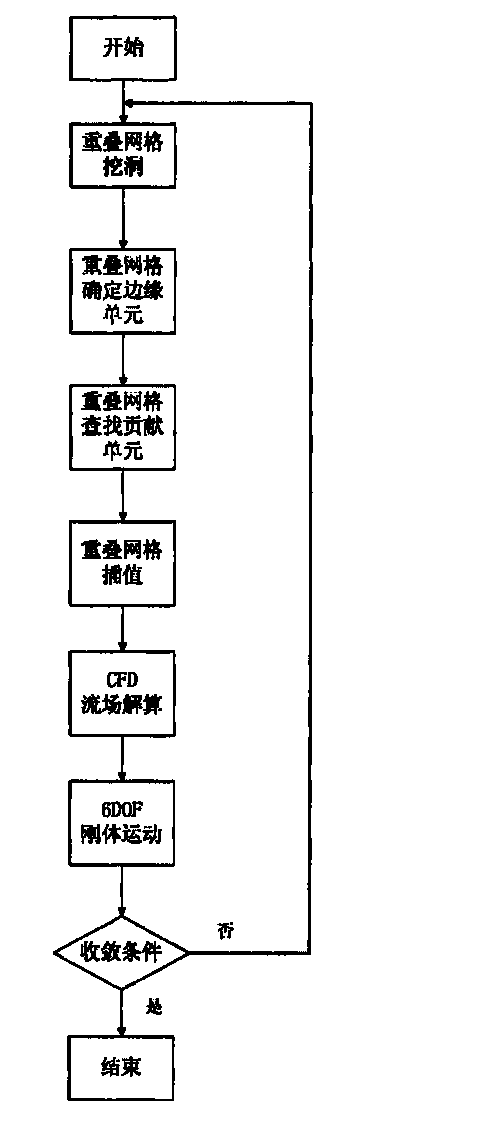
[0029] The implementation process of the present invention will be described in detail below in conjunction with the accompanying drawings. A kind of aircraft multi-body separation simulation method of the present invention, such as figure 1 The method steps shown are as follows:

[0030] (1) Independently generate an unstructured grid for each moving object that makes up the aircraft; the grid shape in the unstructured grid is not limited to tetrahedron, triangular prism or hexahedral grid, and can be any polyhedral grid.

[0031] (2) According to the separation state corresponding to the current moment of the aircraft, perform overlapping grid digging on all unstructured grids generated in step (1), shield the grid units that do not participate in the flow field calculation, and form the hole boundary of the overlapping grid ;

[0032] Figure 4 For applying the present invention to dig hole renderings, Figure 4 a is the mesh of the wing and the pylon, Figure 4 b is t...


PUM


Abstract

Provided is a multi-body separating analogy method of an aircraft. The multi-body separating analogy method comprises (1) enabling each moving object forming the aircraft to respectively independently generate one unstructured grid; (2) performing overlapping-grid hole digging on all the unstructured grids according to a separating state corresponding to the current moment of the aircraft, shielding grid units not participating in flow field calculation, and constructing hole borders of overlapping grids; (3) determining edge units of the overlapping grids; (4) determining contribution units of each edge unit; (5) determining interpolation method from the contribution units to the edge units; (6) calculating a flow field of the aircraft under the current moment, performing six-degree-of-freedom rigid motion equation calculation according to calculating results, and determining displacement of each moving object in the aircraft; and (7) moving the position of the unstructured grid of the each moving object, acquiring a separating state of the aircraft at next moment and carrying out circulating execution from the step (2) until a preset moment reaches.

Description

technical field [0001] The invention relates to a multi-body separation simulation method of an aircraft, which is used for simulating and solving the multi-body separation problems of aircraft bombing, inter-stage separation, and weapon throwing. Background technique [0002] The current computational fluid dynamics CFD technology has been able to calculate the static aerodynamic characteristics and flow field of the aircraft more accurately, and the steady state CFD calculation has become an indispensable means of aircraft engineering design. However, for those flows with strong unsteady effects, such as flapping wings of birds, deflection of control surfaces, relative motion between multiple bodies, etc., it is still difficult to accurately simulate CFD, because these strong unsteady effects are Caused by rapid motion and large displacements of the wall boundary. Although the current CFD technology is capable of handling such unsteady motions, there is still a lot of wor...

Claims


Application Information

Patent Timeline
Patent Type & Authority Patents(China)
IPC IPC(8): G06F17/50B64F5/00
Inventor 刘周周伟江龚安龙
Owner CHINA ACAD OF AEROSPACE AERODYNAMICS
Why Eureka
Try Eureka