Self-centering power chuck of circular arc-shaped groove

An arc groove and self-centering technology, applied in the direction of the chuck, can solve the problems of high processing cost, small claw stroke, complex structure, etc., and achieve the effect of low processing cost, large claw stroke, and simple structure

Inactive Publication Date: 2012-06-06
贺自清
View PDF7 Cites 12 Cited by
  • Summary
  • Abstract
  • Description
  • Claims
  • Application Information

AI Technical Summary

Problems solved by technology

[0002] At present, most of the self-centering chucks used on various machine tools are wire-bevel gear pair or screw pair-bevel gear pair structure. The processing costs of the wire, screw pair, and bevel gear pair are high, and the wire -The bevel gear pair structure has a small claw stroke; most of the self-centering power chucks are wedge-shaped structure, the structure is complex, and the claw stroke is also small

Method used


Image

  • Self-centering power chuck of circular arc-shaped groove
  • Self-centering power chuck of circular arc-shaped groove
  • Self-centering power chuck of circular arc-shaped groove

Examples


Embodiment Construction

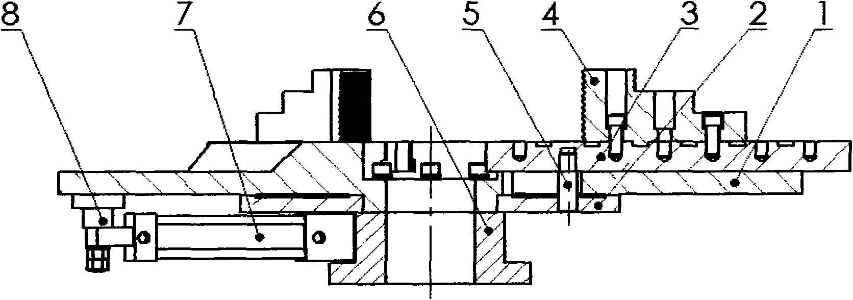
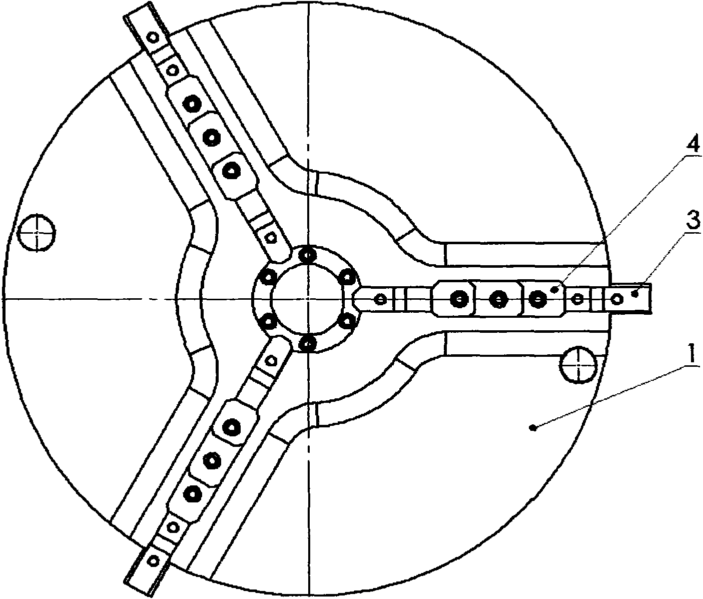
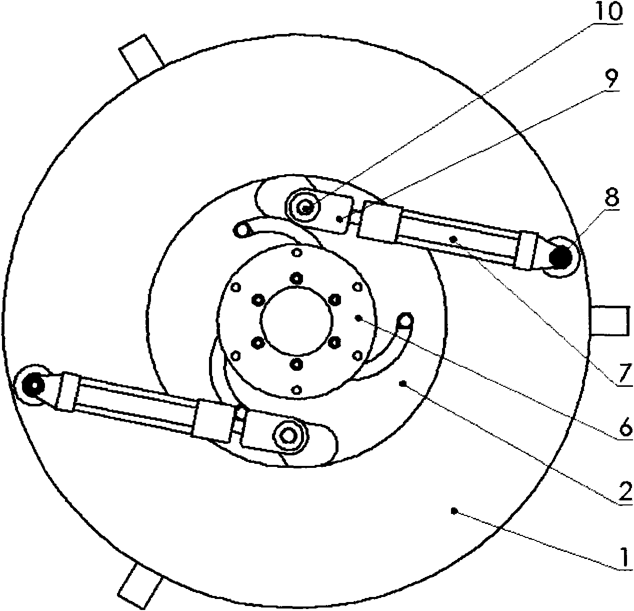
[0019] Referring to the accompanying drawings, the arc groove self-centering power chuck of the present invention will be described in detail below.

[0020] The arc groove self-centering power chuck of the present invention is composed of a chuck body 1, a face plate 2, a trapezoidal slider 3, a claw 4, a pin shaft 5, a connecting flange 6, an oil cylinder 7, an oil cylinder shaft 8, a joint 9, and a joint shaft 10 composition. The faceplate 2 is installed closely below the chuck body 1 and is coaxial with the chuck body 1, the chuck body 1 and the faceplate 2 can rotate mutually, and the trapezoidal slider 3 is installed in the trapezoidal groove on the chuck body 1 and can Sliding in the trapezoidal groove, the pin shaft 5 is fixed under the trapezoidal slider 3, and inserted into the linear long slot hole of the chuck body 1, and also inserted into the arc slot hole of the face plate 2, and the claw 4 can be fixed on the trapezoidal slot. At different positions on the sli...


PUM


Abstract

The invention relates to a self-centering power chuck of a circular arc-shaped groove; a faceplate is closely arranged below a chuck body; a trapezoidal slider is arranged in a trapezoidal groove which is arranged on the chuck body; a pin shaft is fixed below the trapezoidal slider and is inserted in a linear long groove hole of the chuck body and in the circular arc-shaped groove of the faceplate; jaws can be fixed at different positions on the trapezoidal slider; the cylinder body of an oil cylinder is arranged on the chuck body through an oil cylinder shaft, and the cylinder rods of the oil cylinder are arranged on the faceplate through a connector and a connector shaft; a connecting flange is fixedly arranged on the chuck body and is pressed on the faceplate; and the connecting flange can be fixed on a machine tool. Compared with the prior art, the self-centering power chuck of the circular arc-shaped groove has the advantages of simple structure, convenience in processing, low processing cost and large stroke of the jaws.

Description

technical field [0001] The invention relates to a chuck used on a machine tool, in particular to an arc groove self-centering power chuck. Background technique [0002] At present, most of the self-centering chucks used on various machine tools are coil wire-bevel gear pair or screw pair-bevel gear pair structure. The processing costs of the coil wire, screw pair, and bevel gear pair are high, and the coil wire -The bevel gear pair structure has a small claw stroke; most of the self-centering power chucks are wedge-shaped, and its structure is complex, and the claw stroke is also small. Contents of the invention [0003] The object of the present invention is to provide a circular arc groove self-centering power chuck for the above-mentioned deficiencies in the prior art. The stroke of the claw is large, and the clamping range is large. [0004] The present invention can be implemented through the following technical solutions: a self-centering power chuck with arc groov...

Claims


Application Information

Patent Timeline
Patent Type & Authority Applications(China)
IPC IPC(8): B23B31/12B23B31/30
Inventor 贺自清
Owner 贺自清
Why Eureka
Try Eureka