Induction cooking appliance

一种感应加热、烹调器的技术,应用在感应加热烹调器领域,能够解决内部空间温度上升、感应加热烹调器吸气温度上升、无法加热线圈和电子部件冷却等问题,达到抑制温度上升的效果

Active Publication Date: 2012-05-30
PANASONIC INTPROP MANAGEMENT CO LTD
View PDF13 Cites 2 Cited by
  • Summary
  • Abstract
  • Description
  • Claims
  • Application Information

AI Technical Summary

Problems solved by technology

[0007] When both the air intake port and the exhaust port are arranged in a closed space such as the inner space of the cabinet, the exhaust heat after cooling the heating coil and the electronic components is accumulated in the cabinet, so that the The problem of the temperature rise of the internal space
In addition, when the temperature-increased exhaust air is re-inhaled into the internal space of the cabinet, the intake air temperature of the induction heating cooker rises, and the heating coil and the heating coil disposed inside the main body of the induction heating cooker may no longer be able to be heated. Problems with adequate cooling of electronic components

Method used


Image

  • Induction cooking appliance
  • Induction cooking appliance
  • Induction cooking appliance

Examples


Embodiment approach 1

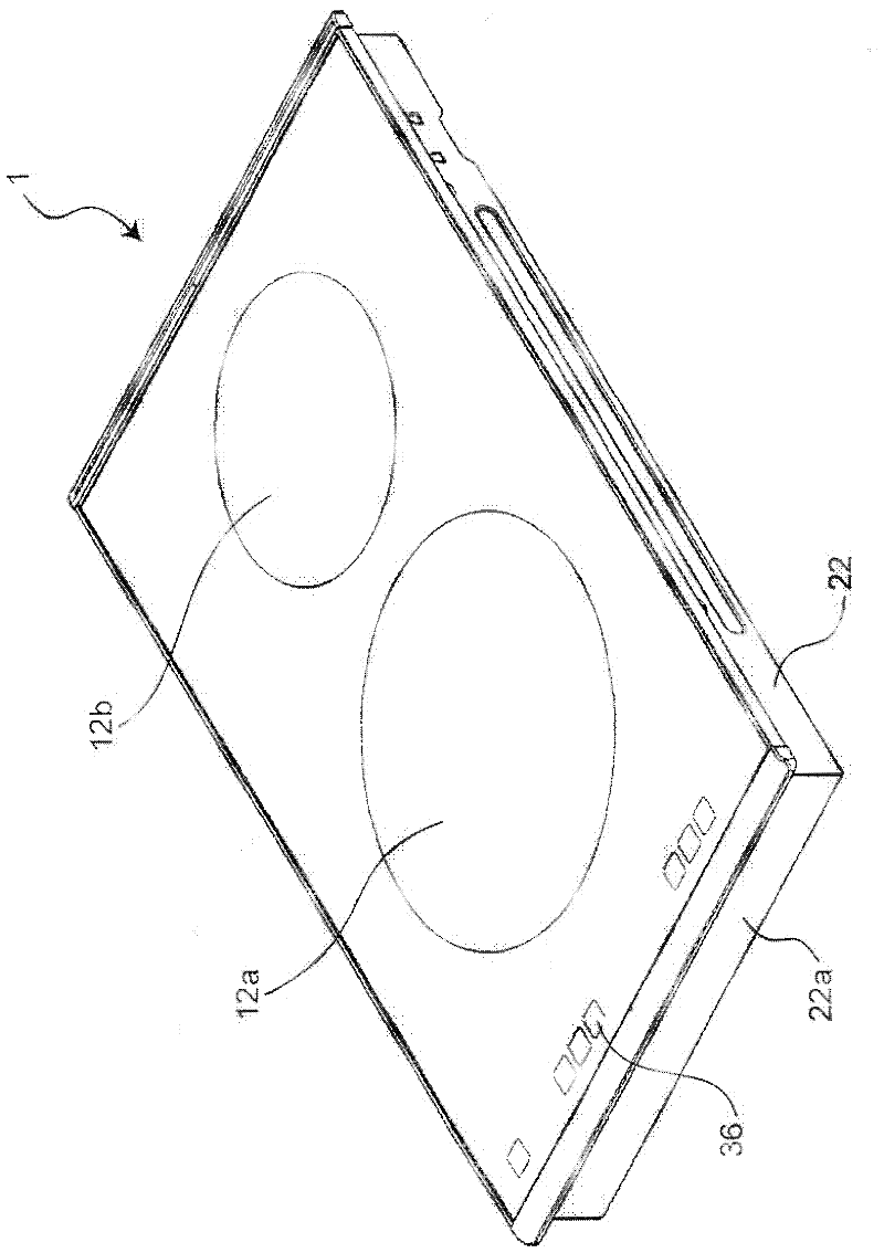
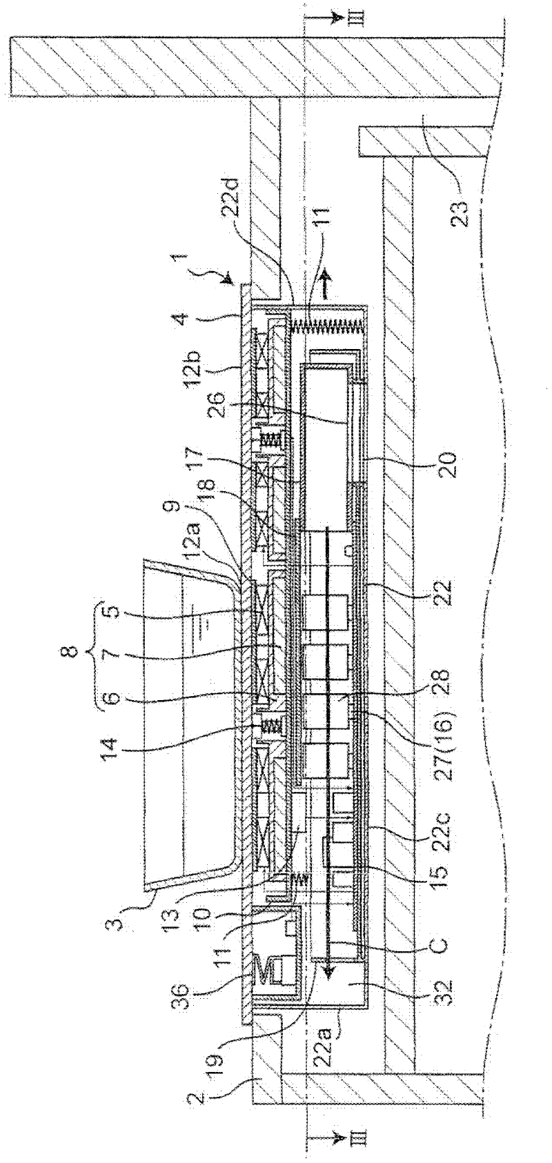
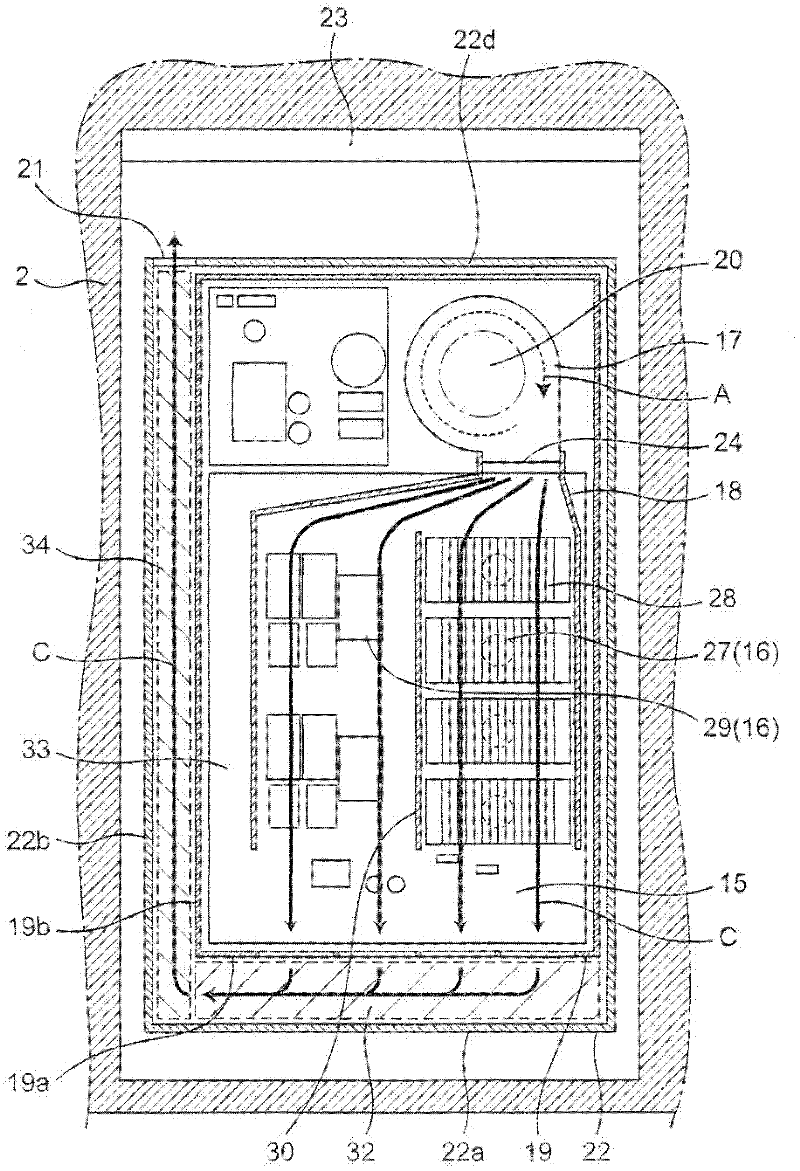
[0072] figure 1 It is a perspective view which shows the whole induction heating cooker which concerns on Embodiment 1 of this invention. figure 2 It is a cross-sectional view showing the installation state where the induction heating cooker according to Embodiment 1 of the present invention is assembled in a cabinet. image 3 It is a horizontal sectional view of the induction heating cooker according to Embodiment 1 of the present invention, and is figure 2 Sectional view of line III-III.

[0073] exist figure 1Among them, on the upper surface of the induction heating cooker 1, a top plate 4 on which a cooking container 3 or the like is placed as an object to be heated is provided. Two heating regions 12a, 12b are formed on the top plate 4 in the first embodiment. In the induction heating cooker 1, heating coils 5 for inductively heating the cooking vessel 3 etc. figure 2 ).

[0074] A heat-resistant resin coil holder 6 is provided below the heating coil 5 . A plu...

Embodiment approach 2

[0154] Hereinafter, an induction heating cooker according to Embodiment 2 of the present invention will be described with reference to the drawings. Figure 4 It is a horizontal sectional view showing the internal structure of the induction heating cooker according to Embodiment 2 of the present invention. In addition, in the induction heating cooker of Embodiment 2, since the basic structure is the same as the induction heating cooker 1 of Embodiment 1 mentioned above, it demonstrates centering on a difference. In the following description of Embodiment 2, constituent elements having the same functions and structures as those of the induction heating cooker 1 of Embodiment 1 are given the same reference numerals, and detailed description thereof is omitted, and the description of Embodiment 1 is followed.

[0155] like Figure 4 As shown, the induction heating cooker according to Embodiment 2 is configured such that the cooling air C from the blower 17 is guided by the duct ...

Embodiment approach 3

[0167] Hereinafter, an induction heating cooker according to Embodiment 3 of the present invention will be described with reference to the drawings. Figure 5 It is a horizontal sectional view showing the internal structure of the induction heating cooker according to Embodiment 3 of the present invention. In addition, in the induction heating cooker of Embodiment 3, since the basic structure is the same as the induction heating cooker 1 of Embodiment 1 mentioned above, it demonstrates centering on a difference. In the following description of Embodiment 3, constituent elements having the same functions and structures as those of the induction heating cooker 1 of Embodiment 1 are given the same reference numerals, and detailed description thereof is omitted, and the description of Embodiment 1 is followed.

[0168] like Figure 5 As shown, in the induction heating cooker according to Embodiment 3, the exhaust port 21 is formed on the back side of the left side wall 22b of the...


PUM


Abstract

Provided is an induction cooking appliance wherein air which has cooled the heat generating components is discharged to atmosphere outside the main body in such a manner that the readmission of discharged air through the admission port is reduced. The direction of the flow of cooling wind which has cooled the heat generating components is changed within the main body, and the cooling wind is discharged through an exhaust port (21) outside a first peripheral wall (19). The flow of cooling wind is straightened within the main body so that the flow reaches a certain level of flow rate when discharged through the exhaust port (21), with the result that the cooling wind is discharged in a particular flow direction and hence the readmission of discharged air through the admission port (20) is reduced. As a result, the induction cooking appliance is not much affected by obstacles at the exhaust port and can be used with a kitchen cabinet having the admission and exhaust ports on the rear side thereof, meaning that the user is not exposed to unpleasant exhaust gases and can be in a comfortable kitchen environment and that the induction cooking appliance is relatively unlikely to fail.

Description

technical field [0001] The present invention relates to an induction heating cooker for inductively heating a cooking vessel such as a metal pan as an object to be heated by using a heating coil, and particularly relates to a cooling structure in the induction heating cooker. Background technique [0002] In recent years, induction heating cookers have become popular in kitchens of general households as a safe and clean heat source that does not use fire and does not emit combustion gas. Among the induction heating cookers used in the kitchen, there is known a built-in induction heating cooker in which the main body of the induction heating cooker is inserted into an opening formed on the upper surface of a box-shaped cabinet, and the induction heating cooking The main body part of the appliance is arranged inside the cabinet, and the cooking top plate constituting the upper surface of the induction heating cooker is arranged in a state exposed on the upper surface of the ca...

Claims


Application Information

Patent Timeline
Patent Type & Authority Applications(China)
IPC IPC(8): H05B6/12
CPCH05B2206/022H05B6/1263
Inventor 松井英史片冈章重冈武彦日下贵晶小川贤治
Owner PANASONIC INTPROP MANAGEMENT CO LTD
Why Eureka
Try Eureka