
Multicomponent cartridge with venting apparatus

A multi-component, ventilation element technology for use in exhaust devices, containers with multiple items, devices for applying liquids to surfaces, etc.

Inactive Publication Date: 2013-12-04
SULZER MIXPAC AG
View PDF1 Cites 0 Cited by
  • Summary
  • Abstract
  • Description
  • Claims
  • Application Information

AI Technical Summary

Problems solved by technology

[0004] Disadvantageously in this construction, such an arrangement of ventilation slots is ineffective when filling via the corresponding discharge nozzle

Method used


Image

  • Multicomponent cartridge with venting apparatus
  • Multicomponent cartridge with venting apparatus
  • Multicomponent cartridge with venting apparatus

Examples


Embodiment Construction

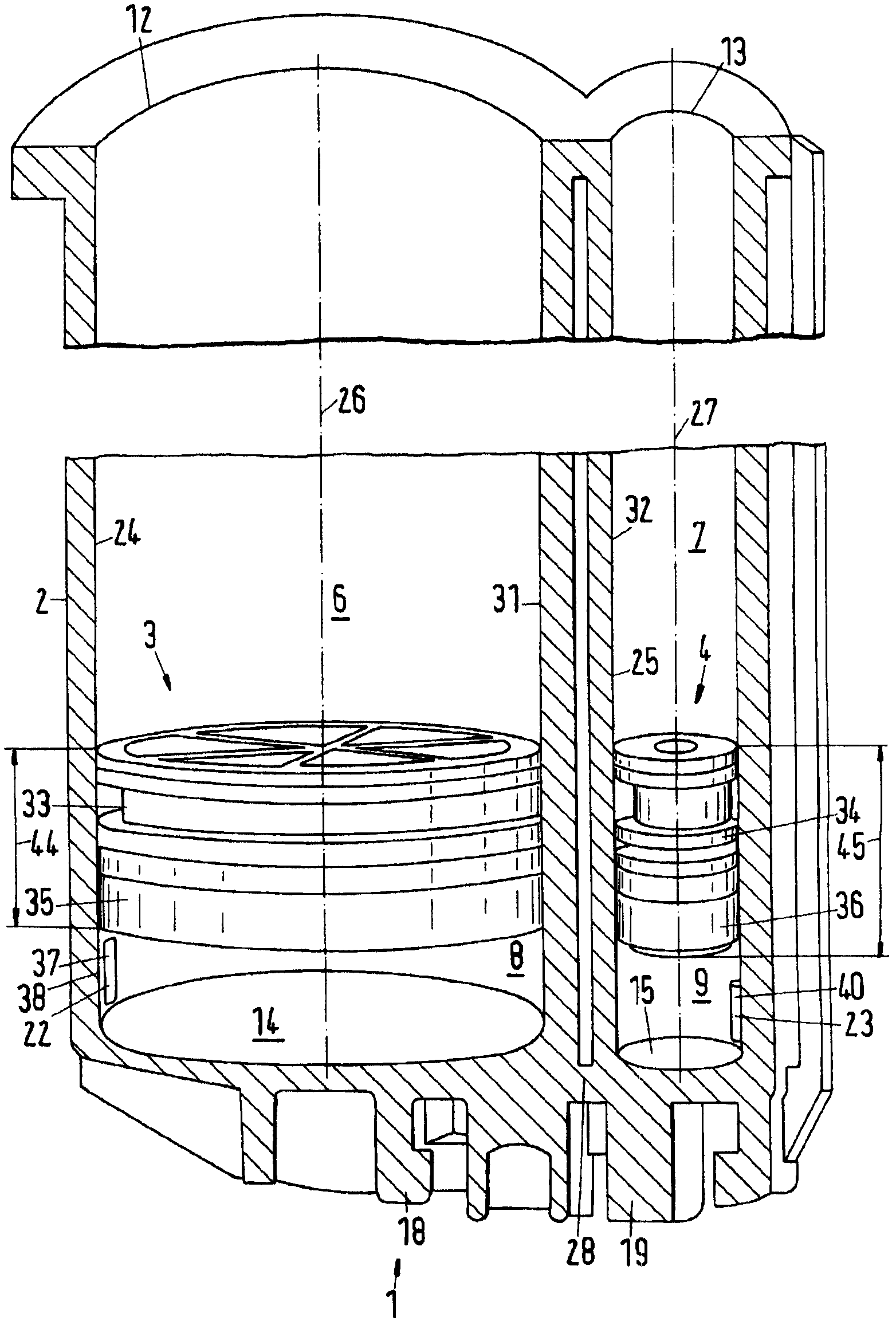
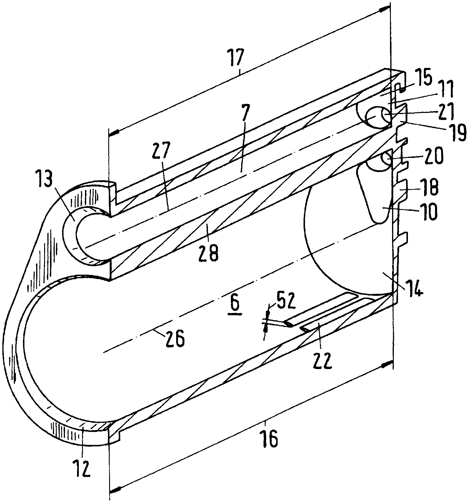
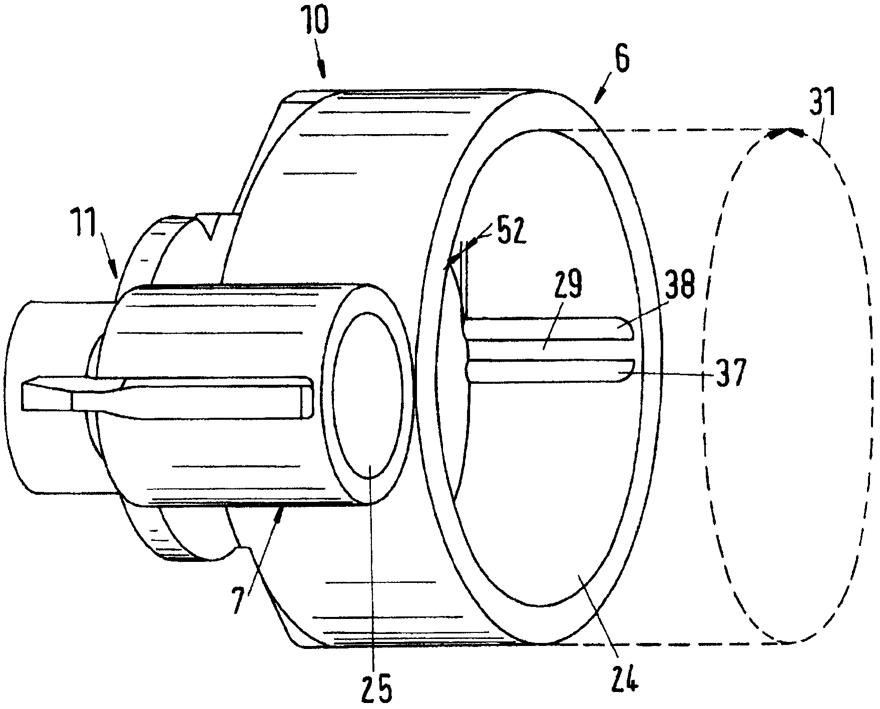
[0030] figure 1A first embodiment of a multicomponent cartridge 1 according to the invention is shown. In particular, such multi-component cartridges are intended to contain metered filling materials comprising at least two components, which are not allowed to come into contact with each other prior to their joint use. The multicomponent cartridge 1 comprises a first storage chamber 6 for a first component 8 , a second storage chamber 7 for a second component 9 . The first storage chamber 6 is separated from the second storage chamber 7 such that the two components do not come into contact with each other. Such components often interact with each other once they come into contact with each other, wherein chemical reactions may take place. Interaction of components is often a desired effect in an application, however as long as the components are stored this interaction is not desired. Each of the components may of course again comprise a mixture of substances. The multicom...


PUM


Abstract

A multicomponent cartridge includes a first storage chamber for a first component and a second storage chamber for a second component. The first storage chamber is separate from, and arranged next to, the second storage chamber. A first piston is movably received in the first storage chamber. A second piston is movably received in the second storage chamber. Each of the first or second storage chambers has a respective filling end and a respective discharge end. The storage chambers are connected to one another at at least the discharge end. The storage chambers have inner walls with the discharge end opening into a discharge element in an opening aperture. A venting element is upstream of the corresponding opening aperture at at least one of the inner walls, with the venting element extending over a maximum of one third of a longitudinal dimension of the storage chamber.

Description

technical field [0001] The invention relates to a multicomponent cartridge which is suitable for the simultaneous delivery of at least two components, wherein the delivery of the two components takes place separately. The two components can be mixed just before use in order to be supplied as a mixture for their intended use. Background technique [0002] A multicomponent cartridge of this type is already known from document WO 9105731 . The multi-component cartridge includes first and second cavities each fillable with a respective component. The first cavity and the second cavity have a cylindrical shape and are arranged adjacent to each other. Each of the two cavities opens into a discharge nozzle through which one of the components is discharged in each case. A static mixer, in which the components respectively discharged through the discharge nozzles are mixed with one another, can be coupled to the two discharge nozzles. Instead of a static mixer, a closing element ...

Claims


Application Information

Patent Timeline
Patent Type & Authority Patents(China)
IPC IPC(8): B65D81/32
CPCB65D81/325B65D2205/04B05C17/00566F02B57/06Y02W10/20
Inventor P·朱特齐
Owner SULZER MIXPAC AG
Learn More