Conductor handling tool and a method of applying an electrically insulating material
A technology of electrical insulating materials and conductors, which is applied in the manufacture of circuits, electrical components, inductors/transformers/magnets, etc., and can solve the problems that wires cannot reliably disperse glass fibers and cannot disperse glass fibers, etc.
- Summary
- Abstract
- Description
- Claims
- Application Information
AI Technical Summary
Problems solved by technology
Method used
Image
Examples
no. 1 example
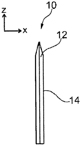
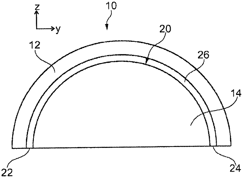
[0031] refer to Figures 1a to 1c , a first embodiment of the conductor handling tool will be described. exist Figures 1a to 1c , in the y direction ( Figure 1a ), from the x direction ( Figure 1b ) and from the z direction ( Figure 1c ) shows the conductor handling tool in the corresponding side view. In addition, the corresponding directions x, y and z are marked in the respective figures. These directions are orthogonal with respect to each other.
[0032] The conductor handling tool has a tool body 10, a conductor receiving opening 20 (formed as a slot 26 with two open ends 22, 24) and a tapered cutting edge 12 extending in a plane. The above directions x, y and z are defined such that the plane in which the blade 12 extends is the y-z plane.
[0033] Tool body 10
[0034] The tool body 10 is shaped as a plate whose extension in one direction (x-direction) is smaller than its extension in the other directions (y-direction and z-direction). The plate has a se...
no. 2 example
[0062] Figures 3a to 3c A second embodiment of the conductor handling tool is shown in a corresponding side view from the y, x and z directions, respectively. Figure 3a and 3c corresponds to Figures 1a to 1c , and the same or similar elements are denoted by the same reference numerals. Hereinafter, only relative to the first embodiment ( Figures 1a to 1c ) difference.
[0063] exist Figures 3a to 3c In the second embodiment of the present invention, the conductor receiving opening 20 is formed as a slot 28 having an open end 29 (rather than as referring to Figure 1b The slit 26 in the first embodiment).
[0064] The conductor receiving opening or slot 28 is form-fit to the shape of the coil lug for receiving the coil lug therein. Here, "form fit" means that the slot 28 is sized so that the main part of the sheet can be inserted therein, and that the slot 28 fits the contour of the sheet so that the inserted part is held in the slot by the shape of the slot 28 . S...
no. 3 example
[0069] according to Figure 4a , 4b In another general aspect shown in and 5, the conductor handling tool may further include conductor securing means adapted to cooperate with the conductor receiving opening to secure a conductor received in the conductor receiving opening. The conductor securing means can be, for example, a cover, a cover or an elastic element.
[0070] Figure 4a and 4b A third exemplary embodiment of a conductor handling tool with such a conductor fastening device is shown in a side sectional view from the y direction. The third embodiment is similar to the first embodiment, and the same or similar elements are denoted by the same reference numerals.
[0071]Similar to in the first embodiment, the conductor receiving opening is formed as a slit 26 with an opening side. Furthermore, it has a cover 30 adapted to close the open side of the slit 26 as conductor fixing means. Here, in order to close the open side, the cover 30 has a sliding guide 32 to al...
PUM
| Property | Measurement | Unit |
|---|---|---|
| diameter | aaaaa | aaaaa |
Abstract
Description
Claims
Application Information
 - R&D
- Intellectual Property
- Life Sciences
- Materials
- Tech Scout
- Unparalleled Data Quality
- Higher Quality Content
- 60% Fewer Hallucinations
Browse by: Latest US Patents, China's latest patents, Technical Efficacy Thesaurus, Application Domain, Technology Topic, Popular Technical Reports.
© 2025 PatSnap. All rights reserved.Legal|Privacy policy|Modern Slavery Act Transparency Statement|Sitemap|About US| Contact US: help@patsnap.com


