


Quick Research
Generate reliable direction feasibility study reports for your R&D in just a few steps.

Technical Q&A
Discover and master advanced knowledge NOW. Basics, ideas, possibilities, all at once.

Find Solutions
As an expert in R&D theories, this can generate solutions to your technical problems instantly.

Evaluate Feasibility
Analyze your overall solution with one click, know your potential R&D risks in advance.

Monitor Landscape
Get weekly tech updates, stay abreast of the latest tech innovations and key insights.
Multi-shaft drive device
A multi-axis drive and action technology, applied in the direction of transmission, gear transmission, transmission control, etc., can solve the problems of light weight and space saving of the output shaft, unfavorable economy of the electromagnetic clutch, etc., and achieve lightweight space Effect
- Summary
- Abstract
- Description
- Claims
- Application Information
AI Technical Summary
Problems solved by technology
Method used
Image


Examples
no. 2 Embodiment approach
[0099] Figure 5 as well as Figure 6 The second embodiment of the present invention is shown. This second embodiment is a state in which the rotation axis of the motor 10 is provided so as to be perpendicular to the rotation axis of the first input gear 12 in the configuration of the above-mentioned first embodiment.
[0100] At the front end of the motor shaft 11 of the motor 10, such as Figure 6 As shown, the third input gear 11a constituting a bevel gear is fixed. On the other hand, an input shaft 16 is fixed to the center of the first input gear 12, and a fourth input gear 16a constituting a bevel gear meshing with the third input gear 11a is fixed to the tip of the input shaft 16.
[0101] In this second embodiment, when the motor 10 rotates, the rotation of the motor shaft 11 is transmitted from the third input gear 11a to the fourth input gear 16a, the first input gear 12 rotates, and the second input gear 12 meshing with the first input gear 12 rotates. The input...
no. 6 Embodiment approach
[0121] [7] The sixth embodiment: Figure 12 to Figure 16
[0122] (1) Configuration of the sixth embodiment
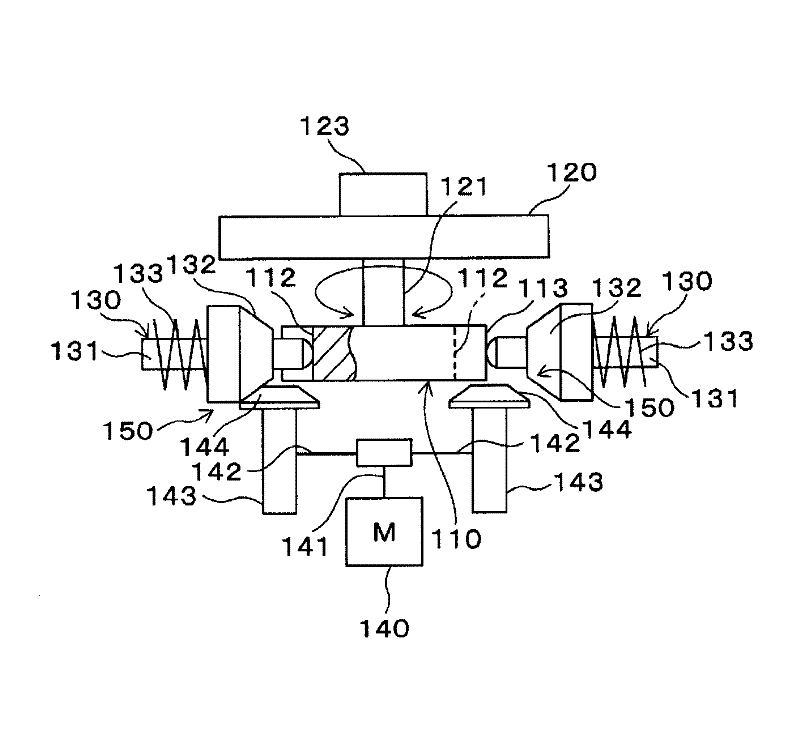
[0123] Figure 12 as well as Figure 13 A multi-axis drive device according to the sixth embodiment is shown. Reference numeral 110 in these figures is a cam member (option member). The cam member 110 is a rectangular plate-shaped member that is long in the horizontal Y direction, and is supported by a guide support member not shown in the longitudinal direction (Y direction, Figure 13 The positive and negative directions of the medium paper) can move freely. Both sides of the cam member 110 along the longitudinal direction are cam surfaces 111 , and a plurality of concave portions 112 opened in the thickness direction are formed at predetermined positions on the cam surface 111 . Moreover, both sides of the concave portion 112 of the cam surface 111 are convex portions 113 along the Y direction. The running part from the concave portion 112 to the convex porti...
no. 7 Embodiment approach
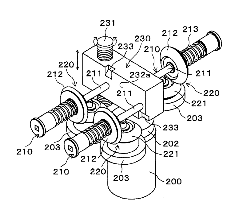
[0143] [8] The seventh embodiment: Figure 17 ~ Figure 19
[0144] The cam member 230 of the seventh embodiment is formed in a rectangular parallelepiped shape, and is supported and held by a guide member not shown. Figure 17 Move up and down in poses where the mid-length direction is horizontal. A turntable shaft 231 having threads formed on its outer peripheral surface is screwed to one end of the cam member 230 so as to penetrate from above. A disc-shaped turntable (not shown) is fixed concentrically to the upper end of the turntable shaft 231 , and when the turntable is rotated, the cam member 230 moves upward or downward according to the rotation direction. That is, the ball screw mechanism is constituted by the turntable shaft 231 and the cam member 230 .
[0145] Recesses 233 are formed on both side surfaces 232a and 232b of the cam member 230 via slopes. The number of recesses 233 and the formation locations are arbitrary. In this case, the upper end and lower end...
PUM
 Abstract
Description
Claims
Application Information
 - R&D Engineer
- R&D Manager
- IP Professional
- Industry Leading Data Capabilities
- Powerful AI technology
- Patent DNA Extraction
Browse by: Latest US Patents, China's latest patents, Technical Efficacy Thesaurus, Application Domain, Technology Topic, Popular Technical Reports.
© 2024 PatSnap. All rights reserved.Legal|Privacy policy|Modern Slavery Act Transparency Statement|Sitemap|About US| Contact US: help@patsnap.com