Phase-locked loop
A phase-locked loop and phase detector technology, applied in the direction of automatic power control, electrical components, etc., can solve the problems of prolonged locking time of the loop 20
- Summary
- Abstract
- Description
- Claims
- Application Information
AI Technical Summary
Problems solved by technology
Method used
Image
Examples
Embodiment Construction
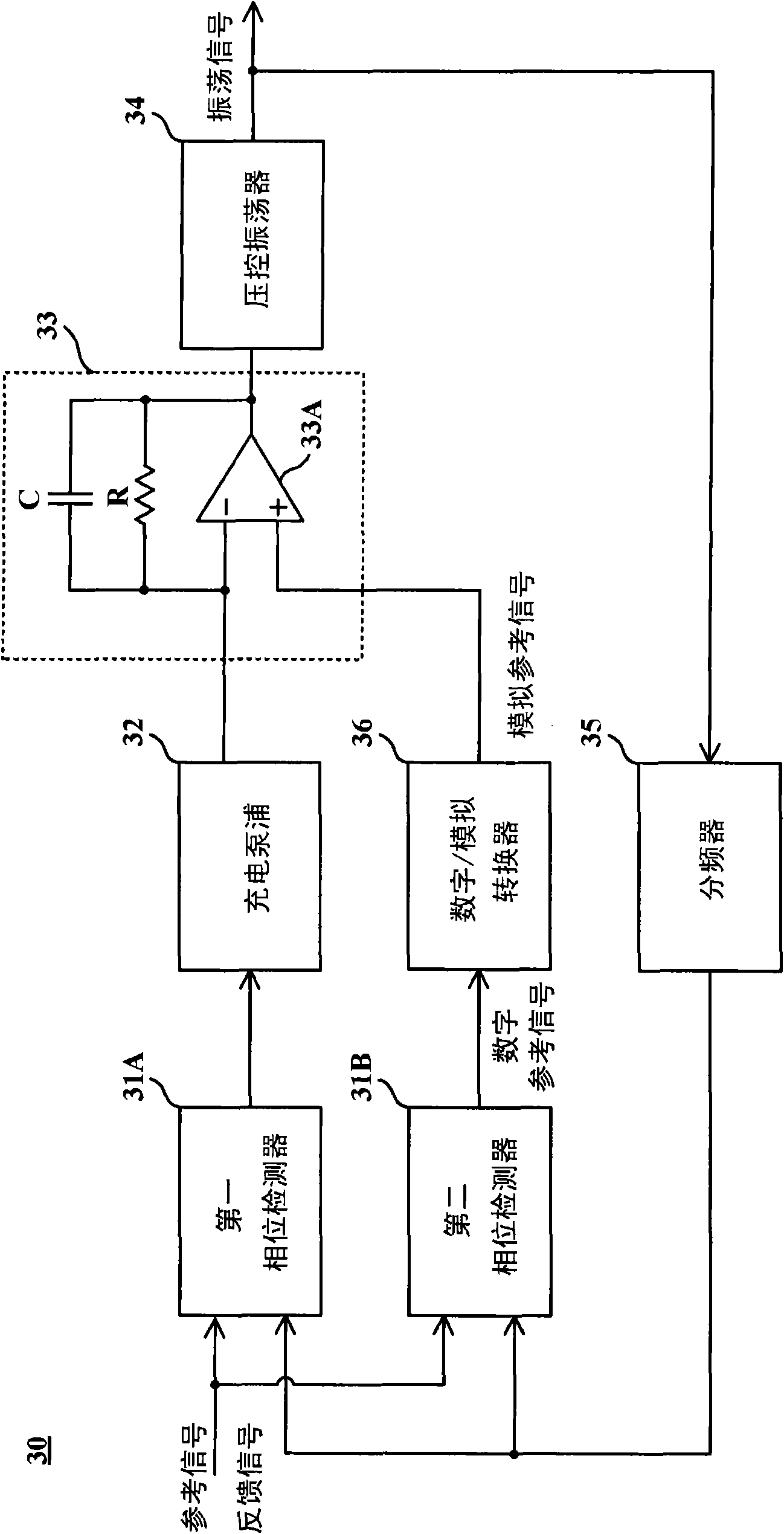
[0031] According to the first specific embodiment of the present invention is image 3 The phase-locked loop is shown. This loop 30 includes two-phase detectors 31A and 31B, a charge pump 32, an active filter 33 made up of a resistor R, a capacitor C, and an operational amplifier 33A, a voltage-controlled oscillator 34, a frequency divider 35, and a Digital / Analog Converter 36.
[0032] Such as image 3 As shown, the active filter 33 includes a first input terminal connected to the charge pump 32 , a second input terminal connected to the digital / analog converter 36 , and an output terminal for providing a control signal. The capacitor C and the resistor R are coupled in parallel between the first input terminal and the output terminal. The function of the voltage controlled oscillator 34 is to generate an oscillation signal according to the control signal. The frequency divider 35 is responsible for dividing the frequency of the oscillating signal to generate a feedback s...
PUM
 Abstract
Description
Claims
Application Information
 - R&D
- Intellectual Property
- Life Sciences
- Materials
- Tech Scout
- Unparalleled Data Quality
- Higher Quality Content
- 60% Fewer Hallucinations
Browse by: Latest US Patents, China's latest patents, Technical Efficacy Thesaurus, Application Domain, Technology Topic, Popular Technical Reports.
© 2025 PatSnap. All rights reserved.Legal|Privacy policy|Modern Slavery Act Transparency Statement|Sitemap|About US| Contact US: help@patsnap.com


