Fixing device and image forming apparatus using the same
An image and fixing roller technology, which is applied in the field of image forming equipment and fixing devices, can solve problems such as fixing failure and heat energy loss of fixing devices, and achieve the effects of preventing heat radiation, preventing heat leakage, and reducing heat loss
- Summary
- Abstract
- Description
- Claims
- Application Information
AI Technical Summary
Problems solved by technology
Method used
Image
Examples
example 1
[0120] Next, an example of the fixing unit 12 of the present embodiment will be described with reference to the drawings.
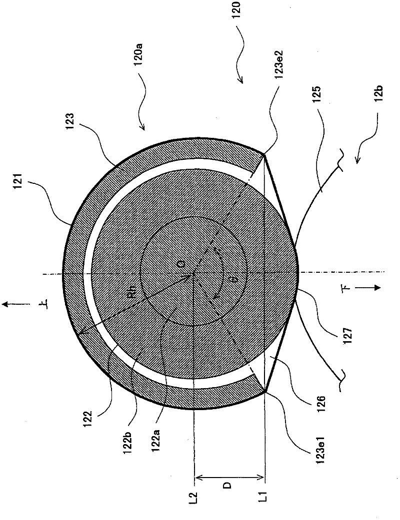
[0121] image 3 is a schematic diagram showing the configuration of Example 1 of the fixing member constituting the fixing unit of the present embodiment. Figure 4A It is a schematic diagram showing the layered structure of the heating member constituting the fixing member of the fixing unit of the present embodiment. Figure 4B is a schematic plan view showing the pattern of the heating member.
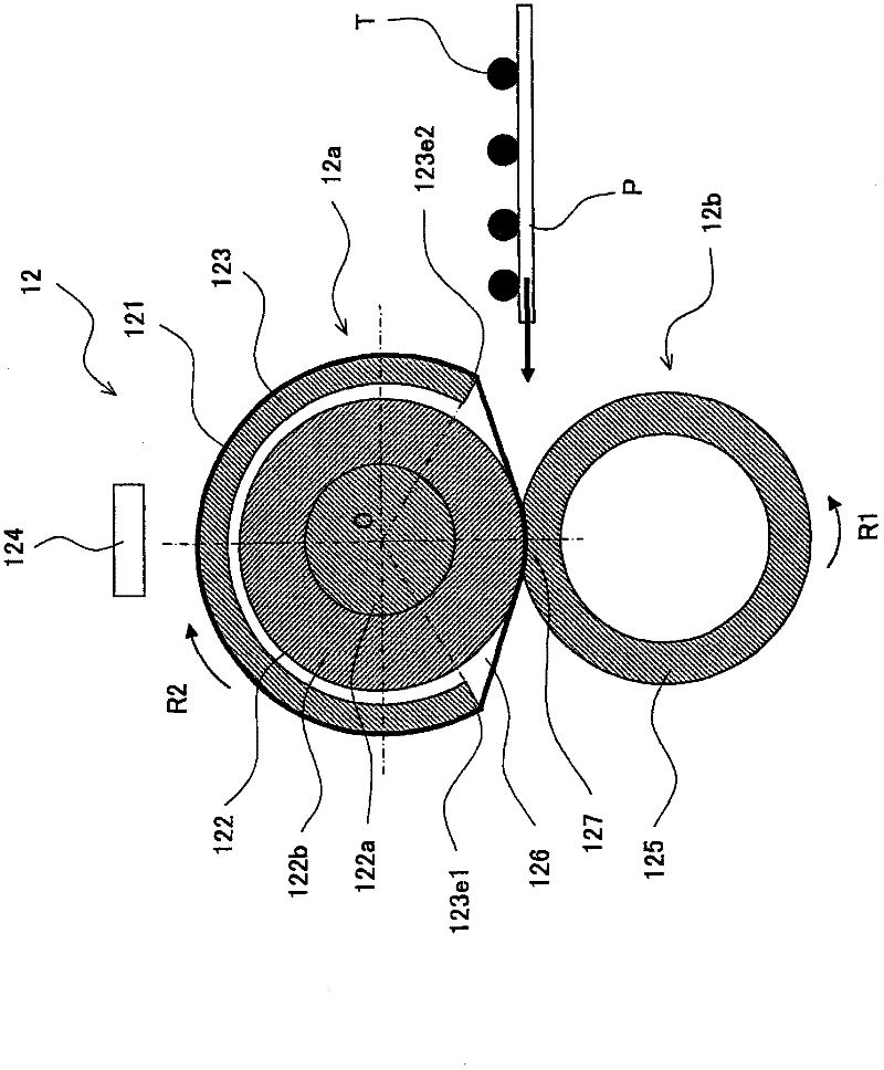
[0122] The fixing unit 120 of Example 1 has the same overall configuration as that of the fixing unit 12 of the embodiment. In the description of the fixing unit 120 , the same components as those of the fixing unit of the embodiment are assigned the same reference numerals and will not be described again.
[0123] In the fixing unit 120 of Example 1, as the fixing belt 121 of the fixing member 120a, a belt-shaped member having a diameter of 36 mm and made o...
example 2
[0143] Next, another configuration of the fixing unit 12 of the present embodiment will be described using Example 2 with reference to the drawings.
[0144] Figure 5 is a schematic diagram showing the configuration of Example 2 of the fixing member constituting the fixing unit of the present embodiment. Figure 6 is a schematic plan view showing the pattern of the heating member of the fixing unit.
[0145] The fixing unit 220 of Example 2 has the same configuration as that of the fixing unit of Example 1 except for the structure of the heating member 223 . Therefore, in the description of the fixing unit 220 , the same components as those of the fixing unit of Example 1 are assigned the same reference numerals and will not be described again.
[0146] Such as Figure 5 As shown, the fixing unit 220 of Example 2 is modified so that the distribution of heat generation from the heating member 223 (heater: curved plate-shaped heat generator) is non-uniform with respect to th...
example 3
[0158] Next, another configuration of the fixing unit 12 of the present embodiment will be described using Example 3 with reference to the drawings.
[0159] Figure 7 is a schematic diagram showing the configuration of Example 3 of the fixing member constituting the fixing unit of the present embodiment.
[0160] The fixing unit 320 of Example 3 has the same configuration as that of the fixing unit of Example 1 except for the configuration of the insulating member 330 . Therefore, in the description of the fixing unit 320 , the same components as those of the fixing unit of Example 1 are assigned the same reference numerals and will not be described again.
[0161] Such as Figure 7 As shown, in the fixing unit 320 of Example 3, the insulating member 330 shielding the outer peripheral side of the heating member 123 by the fixing belt 121 is disposed close to the outer peripheral side of the fixing belt 121 within the range where the fixing belt 121 contacts the heating memb...
PUM
 Abstract
Description
Claims
Application Information
 - R&D
- Intellectual Property
- Life Sciences
- Materials
- Tech Scout
- Unparalleled Data Quality
- Higher Quality Content
- 60% Fewer Hallucinations
Browse by: Latest US Patents, China's latest patents, Technical Efficacy Thesaurus, Application Domain, Technology Topic, Popular Technical Reports.
© 2025 PatSnap. All rights reserved.Legal|Privacy policy|Modern Slavery Act Transparency Statement|Sitemap|About US| Contact US: help@patsnap.com


