Reaction zone structure of light-energy living being culture system and method for culturing light-energy living beings

A technology of biological cultivation and photoreaction, which is applied to the structure of the photoreaction area of ​​the photobiological cultivation system and the field of photobiological cultivation, and can solve the problem of blockage of flow and material liquid circulation devices, inconvenient waste material liquid treatment, and difficult cleaning of the device and other problems, to achieve the effect of uniform mixing of reactants, good air permeability and large reaction specific surface area

Inactive Publication Date: 2012-05-23
ZHEJIANG QICHENG TECH
View PDF5 Cites 3 Cited by
  • Summary
  • Abstract
  • Description
  • Claims
  • Application Information

AI Technical Summary

Problems solved by technology

[0004] However, in the existing flat-plate photobioreactors, the partition structures in the reaction zone of the commonly used reactor are all staggered equal-length partitions, which make the reaction between the feed liquid and the gas insufficient. , at the same time, the treatment of waste material liquid is not convenient enough, and the device is not easy to clean. At the same time, the flow of gas and the circulation of material liquid may also cause unpredictable situations such as blockage of the device due to inconvenient treatment. Therefore, it is urgent to provide A photoreaction zone structure of a photoreactor capable of overcoming the various defects existing in the above-mentioned existing manufacturing technologies and processes and a method for cultivating light-energy organisms

Method used


Image

  • Reaction zone structure of light-energy living being culture system and method for culturing light-energy living beings
  • Reaction zone structure of light-energy living being culture system and method for culturing light-energy living beings
  • Reaction zone structure of light-energy living being culture system and method for culturing light-energy living beings

Examples


Embodiment Construction

[0032] In order to better understand and illustrate the present invention, reference will be made to Figure 1-3 The present invention is further described in detail.

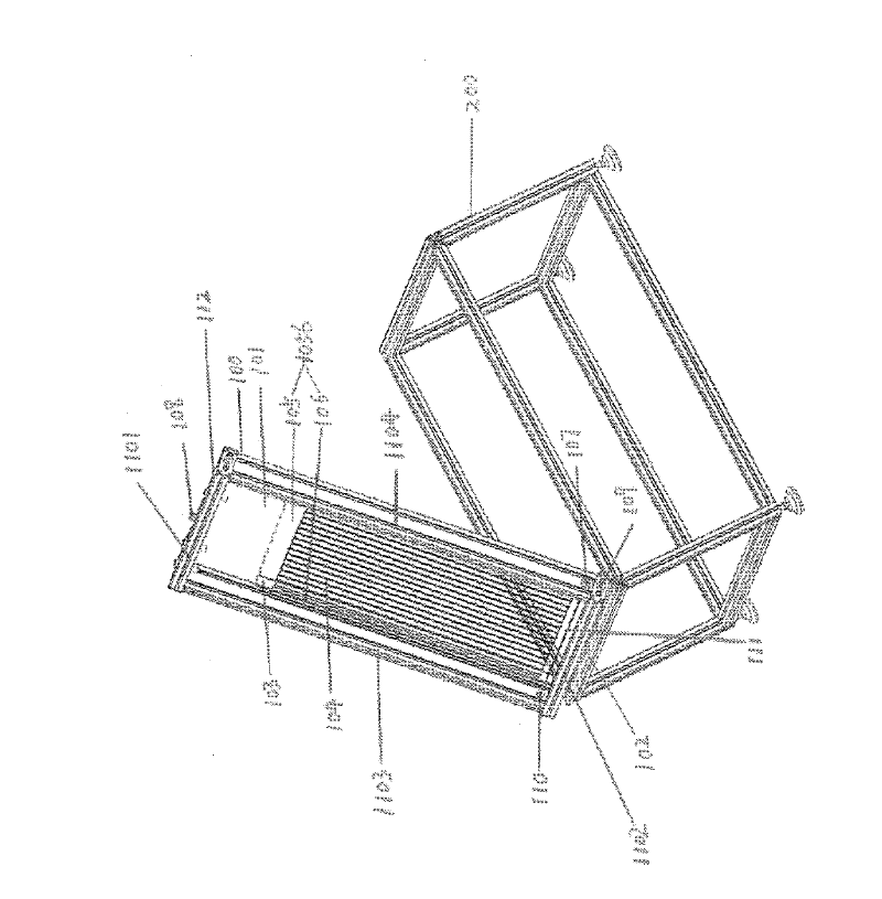
[0033] figure 1 It is a schematic diagram of the overall structure of a photoreactor including a photoreaction zone structure in a photoenergy biological cultivation system according to a preferred embodiment of the present invention. Such as figure 1 As shown, the photoreactor includes a photoreactor body 100 , a mechanical shaft structure 102 and a support base 200 . The main body 100 of the photoreactor is connected to the support base 200 through the mechanical shaft structure 102 . The main body 100 of the photoreactor is a flat cubic closed structure, and is connected to the external system through gas inlets and outlets 107 , 108 and material inlets and outlets 109 , 110 . The main body of the photoreactor is composed of two light-receiving surface panels 101 , a top frame 1101 and a bottom frame 110...


PUM


Abstract

The invention discloses a photoreaction zone structure of a light-energy living being culture system. A photoreactor comprises a photoreactor body, a rotatable mechanical shaft and a supporting base, wherein a photoreaction zone is located inside the photoreactor. The photoreactor is characterized in that the photoreaction zone is provided with a long clapboard structure and a short clapboard structure, which are arranged in parallel; one end of the long clapboard structure and an inner surface of a top border of the photoreactor body are spaced by a certain distance D1; and the short clapboard structure and the inner surface of the top border are spaced by a certain distance D2, wherein D2 is more than D1. The invention further discloses a method for culturing light-energy living beings.The photoreaction zone structure of the light-energy living being culture system and the method for culturing the light-energy living beings, disclosed by the invention, have the advantages of large photoreaction specific surface area, good air permeability, uniformity in reactant mixing, and good circularity.

Description

technical field [0001] The invention relates to the field of photobiological cultivation, in particular to a photoreaction zone structure of a photobiological cultivation system and a method for cultivating photobiological. Background technique [0002] In the existing field of photobiological cultivation, the commonly used cultivation device is a photoreactor, which is usually used in the industrial production of algae, photosynthetic bacteria, moss or other plant cell cultures. These microorganisms can use light energy to convert CO 2 It can be transformed into various organic substances with water, and has the characteristics of high photosynthesis efficiency, strong environmental adaptability, fast reproduction, short growth cycle, no occupation of cultivated land, large-scale, automatic control cultivation (production), etc. [0003] Existing photoreactors usually use flat-plate photobioreactors. This kind of photoreactor has the advantages of large specific surface are...

Claims


Application Information

Patent Timeline
IPC IPC(8): C12M1/00C12M1/18C12M1/10C12M1/08C12M3/00C12N1/12C12N1/20C12N5/04
CPCC12M23/48C12M27/10C12M21/02C12M47/04
Inventor 范文俊徐志农郑晓光
Owner ZHEJIANG QICHENG TECH
Why Eureka
Try Eureka