Constructed shaft element, particularly a constructed camshaft for valve controlled internal combustion engines

A shaft component and engine technology, applied in the direction of engine components, machines/engines, rigid shaft couplings, etc., can solve the problems of force locking reduction, loss of tightening force, clearance, etc., and achieve the effect of simple cost and reduced noise emission

Active Publication Date: 2012-05-16
AUDI AG
View PDF10 Cites 13 Cited by
  • Summary
  • Abstract
  • Description
  • Claims
  • Application Information

AI Technical Summary

Problems solved by technology

However, there is a danger in said deformation that play is created and thus a loss of tightening force, which in turn results in a positive (horizontal) and / or force-locked (horizontal) connection between the shaft and the hub. ) reduction

Method used


Image

  • Constructed shaft element, particularly a constructed camshaft for valve controlled internal combustion engines
  • Constructed shaft element, particularly a constructed camshaft for valve controlled internal combustion engines
  • Constructed shaft element, particularly a constructed camshaft for valve controlled internal combustion engines

Examples


Embodiment Construction

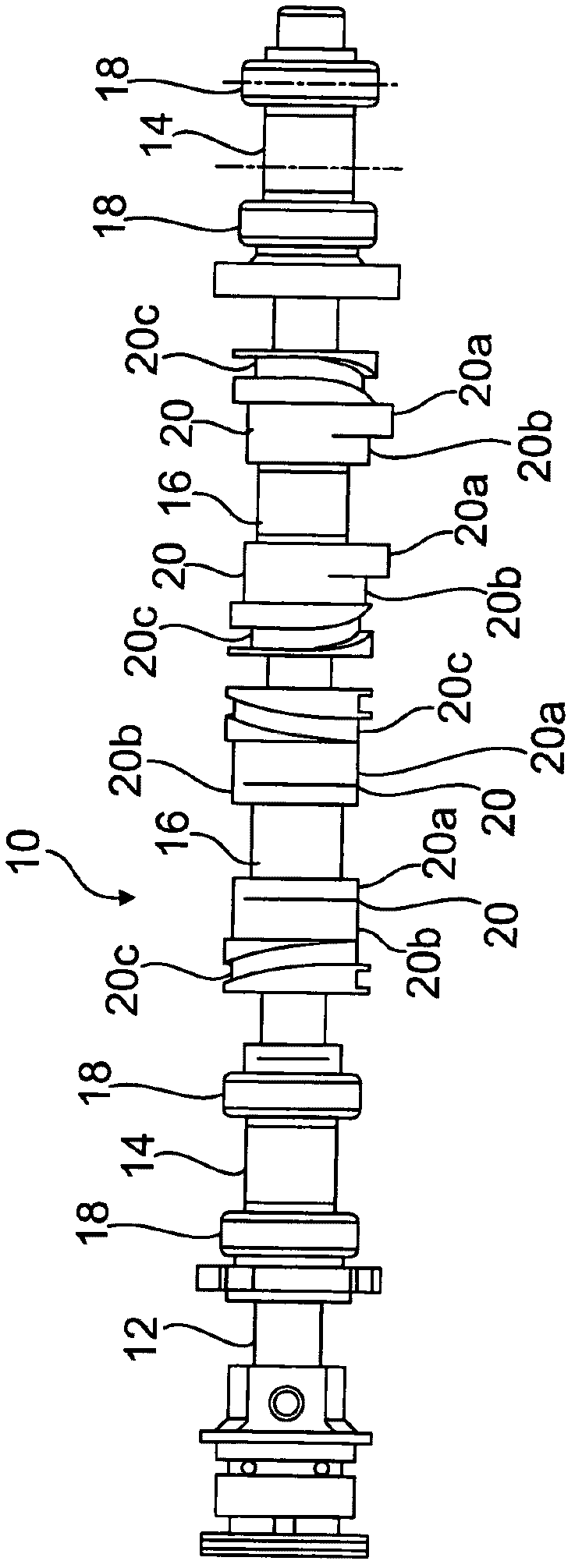
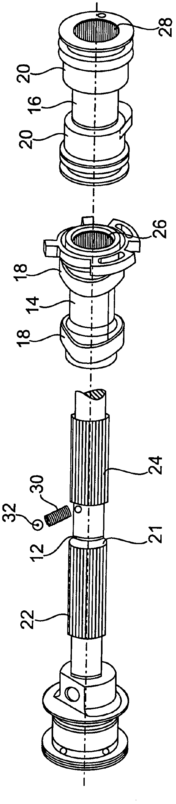
[0019] figure 1 Shown is a camshaft 10 for an engine with partial cylinder shut-off (function), basically comprising an inner shaft 12 drivable by a drive gear (such as a sprocket, not shown), on which are arranged four The pair of cams 18 , 20 formed on the hub bodies 14 , 16 . Only the description necessary for understanding the present invention is given for the camshaft 10 .

[0020] The pair of cams 18 on the hub body 14 are simple fixed cams that each actuate a poppet valve of the engine's valve train / valve train.

[0021] The central pair of cams 20 are switching cams fastened to the hub body 16 , each having a cam profile 20 a and a circularly symmetrical profile 20 b corresponding to the cam base circle. In addition, the pair of cams 20 is provided with an adjacent sliding groove guide 20c by means of which the pair of cams 20 can move axially together with the hub body 16 . In this case, a switching pin (not shown) alternately engages one of the link guides or the...


PUM


Abstract

The present invention relates to a constructed shaft element, particularly a constructed camshaft for valve controlled internal combustion engines, wherein a hub body comprising at least one functional part, particularly at least one cam, is held on a shaft by a form fit connection by means of insertion teeth in the circumferential direction, wherein the insertion teeth comprise shaft teeth formed on the shaft and interacting with hub body teeth formed in a hub body recess. According to the invention, the at least one hub body (14) is held in addition to the circumferential form fit connection by a fixed seat on the shaft (12) implemented by a press fit between a tooth circle of the shaft teeth (22) and a root circle of the hub body teeth (26). The invention further relates to a method for producing a constructed camshaft for valve controlled internal combustion engines.

Description

technical field [0001] The invention relates to a combined / assembled (gebaut) shaft part, in particular a combined camshaft, for a valve-controlled engine according to the preamble of claim 1 and to a combined camshaft according to the preamble of claim 10 A method for manufacturing a modular shaft component described in section. Background technique [0002] Constructions of engines with variable valve control and / or closing of individual cylinders are known in which axially displaceable cams or cam pairs are applied on the camshaft, said cams or cam pairs having, for example, for each poppet valve Two different cam configurations and thus lead to different control times through their switching. If one of the contours is circularly symmetrical (cam base circle), the poppet valve can also be made stationary. If such "switching cams" are combined with non-changeable fixed cams, both variants can already be implemented in a combined fashion on the basis of assembly technolog...

Claims


Application Information

Patent Timeline
Patent Type & Authority Applications(China)
IPC IPC(8): F01L1/047F16D1/10
CPCF16D2001/103F01L1/047B21D53/845F01L2103/00F01L2001/0473F01L2013/0052F16D1/101F01L2820/01F01L13/0042F01L2810/04F01L2303/00Y10T29/49945Y10T74/2101Y10T29/49293Y10T29/49
Inventor P·多林格尔S·托马斯
Owner AUDI AG
Why Eureka
Try Eureka