Phase-locked loop with low-gain voltage-controlled oscillator

A technology of voltage-controlled oscillators and phase-locked loops, which is applied to automatic control of power, electrical components, etc., can solve problems such as system failure and achieve stable phase-locked loops

Inactive Publication Date: 2012-05-16
ALICORP
View PDF5 Cites 1 Cited by
  • Summary
  • Abstract
  • Description
  • Claims
  • Application Information

AI Technical Summary

Problems solved by technology

But when the phase-locked loop is stable, when the control bit Bit_vco of the oscillator corresponding to the oscillation clock of the oscillator changes suddenly, the phase-locked loop needs to be re-locked, and the system will not work normally

Method used


Image

  • Phase-locked loop with low-gain voltage-controlled oscillator
  • Phase-locked loop with low-gain voltage-controlled oscillator
  • Phase-locked loop with low-gain voltage-controlled oscillator

Examples


Embodiment Construction

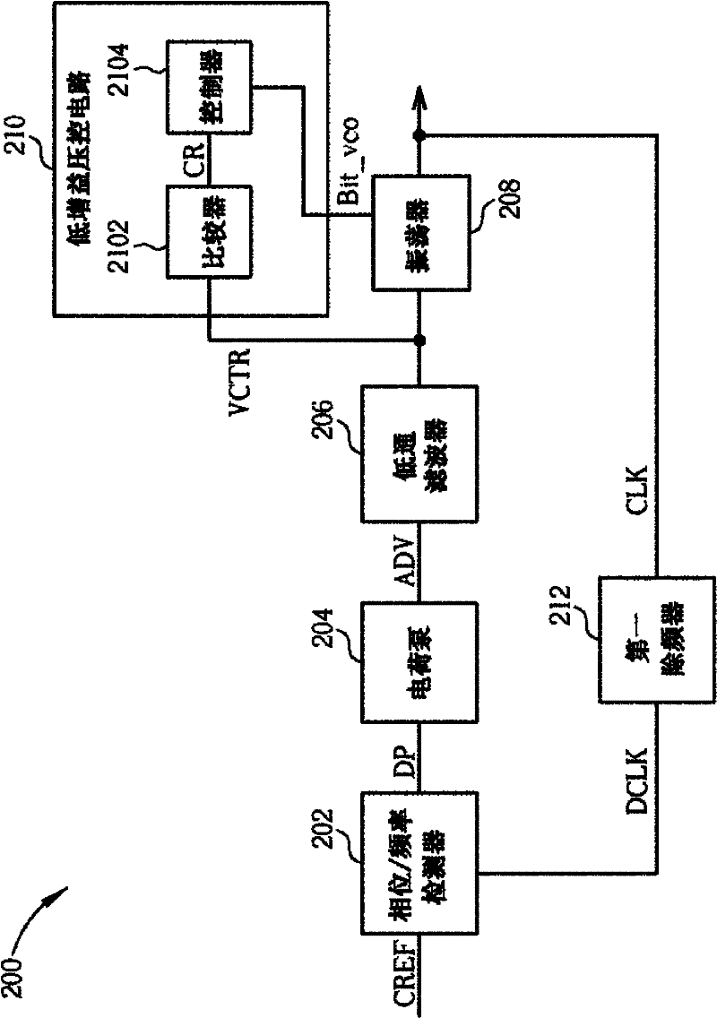
[0063] Please refer to figure 2 , figure 2 It is a schematic diagram illustrating a phase-locked loop 200 with a low-gain voltage-controlled oscillator according to an embodiment of the present invention. The PLL 200 includes a phase / frequency detector 202 , a charge pump 204 , a low-pass filter 206 , an oscillator 208 , a low-gain voltage control circuit 210 and a first frequency divider 212 . The phase / frequency detector 202 is used to generate a detection pulse DP according to the phase / frequency difference between a reference clock CREF and a frequency-dividing oscillation clock DCLK, wherein the detection pulse DP and the phase / frequency difference are linearly proportional. The charge pump 204 is coupled to the phase / frequency detector 202 for generating a detection voltage ADV according to the detection pulse DP; the low-pass filter 206 is coupled to the charge pump 204 for generating an oscillation according to the detection voltage ADV The oscillator control volta...


PUM


Abstract

The invention discloses a method for controlling a low-gain voltage-controlled oscillator, which comprises: setting a control bit of the oscillator as a presetting bit and a control voltage of the oscillator as a presetting value; comparing whether the control voltage of the oscillator exceeds a range of a first group of voltage boundary; if so regulating the preset control bit of the oscillator by a rank, then re-comparing whether the control voltage of the oscillator exceeds the range of the first group of voltage boundary; otherwise changing the first group of voltage boundary to a second group of voltage boundary; comparing whether the control voltage of the oscillator exceeds a range of the second group of voltage boundary; if so regulating the control bit where the oscillator is by a rank, then re-comparing whether the control voltage of the oscillator exceeds the range of the second group of voltage boundary; otherwise regulating the second group of voltage boundary to the first group of voltage boundary, and outputting the control voltage of the oscillator; and the first group of voltage boundary being larger than the second group of voltage boundary.

Description

technical field [0001] The invention relates to a phase-locked loop and its control method, especially a phase-locked loop with a low-gain voltage-controlled oscillator. Background technique [0002] Please refer to Figure 1A , Figure 1A It is a schematic diagram illustrating the process of a low-gain voltage-controlled oscillator from power-on to clock locking in the prior art. Such as Figure 1A As shown, when the oscillator control bit Bit_vco is zero, the oscillator control voltage VCTR slowly rises from the position of circle 0 to the position of circle 1 which is greater than the upper limit VH of the voltage boundary. Therefore, the oscillator control bit Bit_vco jumps to one, and then the oscillator control voltage VCTR slowly rises from the position of circle 2 to the position of circle 3 which is greater than the upper limit VH of the voltage boundary. Until the oscillator control bit Bit_vco is equal to 2, the oscillator control voltage VCTR rises to the positi...

Claims


Application Information

Patent Timeline
Patent Type & Authority Applications(China)
IPC IPC(8): H03L7/08H03L7/187
Inventor 林国凯赵淳安
Owner ALICORP
Why Eureka
Try Eureka