Rotating shaft structure of circuit breaker release

A shaft structure and release technology, applied in the low-voltage electrical field, can solve the problems of limited installation space, deformation of the bracket, inconvenient installation of the shaft body, etc., and achieve the effects of avoiding movement, improving installation, and ensuring the effect of rotation.

Active Publication Date: 2012-05-09
CHANGSHU SWITCHGEAR MFG CO LTD (FORMER CHANGSHU SWITCHGEAR PLANT)
View PDF8 Cites 1 Cited by
  • Summary
  • Abstract
  • Description
  • Claims
  • Application Information

AI Technical Summary

Problems solved by technology

Although this rotating shaft structure can effectively limit the rotating shaft body, because the structure of the aforementioned rotating shaft installation hole for inserting the end of the rotating shaft body on the bracket wall of the bracket shows a fully enclosed full circular hole structure, so in When installing the shaft body on the bracket, the following confusion often arises: since the shaft can only fit with the shaft installation hole in the way of axial penetration, and because the installation space is usually limited, it causes great trouble to the installation of the shaft body. It is inconvenient, and even the bracket is deformed during the installation process, more specifically, the bracket walls with the shaft mounting holes are deformed toward the direction of repelling each other, so when the circuit breaker is working, the shaft body will produce undesired movement In this case, it is difficult to ensure the rotation effect of the shaft body, which will eventually affect the reliability of the circuit breaker.

Method used


Image

  • Rotating shaft structure of circuit breaker release
  • Rotating shaft structure of circuit breaker release
  • Rotating shaft structure of circuit breaker release

Examples


Embodiment Construction

[0015] In order to enable the examiners of the patent office, especially the public, to understand the technical essence and beneficial effects of the present invention more clearly, the applicant will describe in detail the following in the form of examples, but none of the descriptions to the examples is an explanation of the solutions of the present invention. Any equivalent transformation made according to the concept of the present invention which is merely formal but not substantive shall be regarded as the scope of the technical solution of the present invention.

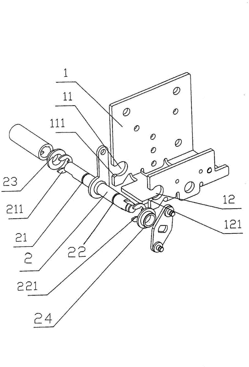
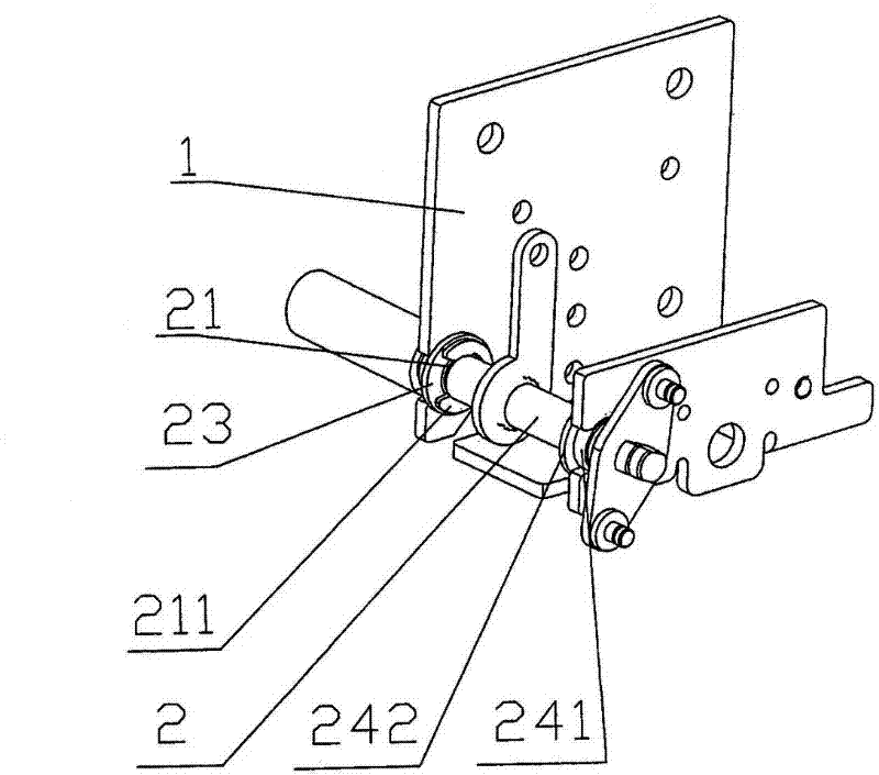
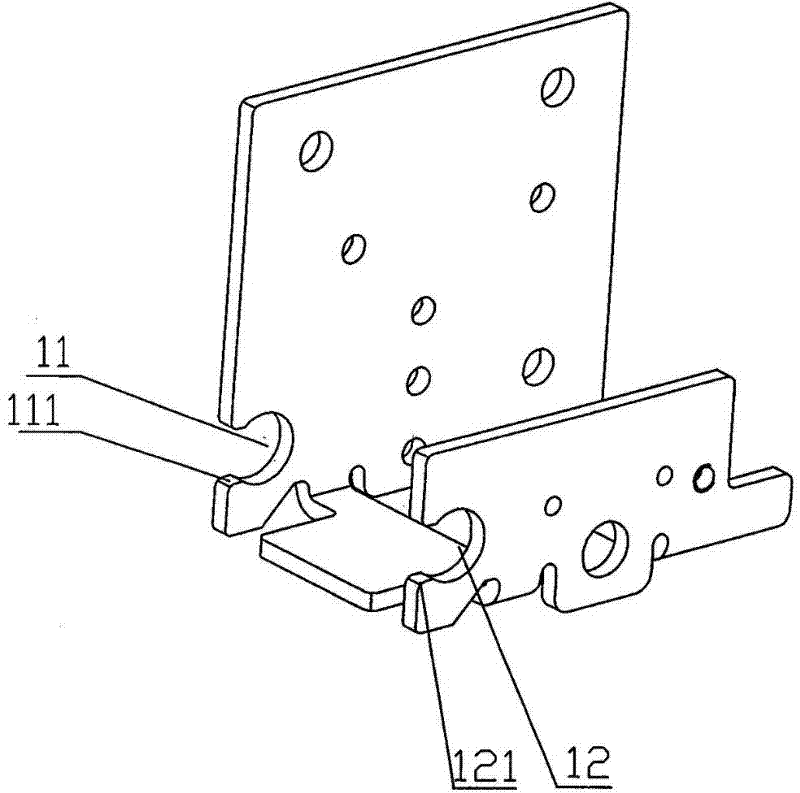
[0016] Please see figure 1 and figure 2 and image 3 , a bracket 1 that constitutes the rotating shaft structure of the circuit breaker release is given, a first shaft mounting hole 11 is opened on the bracket wall on one side of the bracket 1, and a first shaft mounting hole 11 is opened on the bracket wall on the other side of the bracket 1. And a second shaft installation hole 12 is opened at a p...


PUM


Abstract

The invention relates to a rotating shaft structure of a circuit breaker release and belongs to the field of low-voltage electrical techniques. The rotating shaft structure of the circuit breaker release comprises a support and a rotating shaft body. A first rotating shaft installation hole is arranged on a support wall on one side of the support. The rotating shaft body is arranged in the first rotating shaft installation hole. The rotating shaft structure of the circuit breaker release is characterized in that a first open groove is formed on one side of the first rotating shaft installation hole towards the rotating shaft body, the width of the first open groove is smaller than the diameter of the first rotating shaft installation hole and is larger than the diameter of the matching section of the rotating shaft body, wherein the matching section is used for being matched with the first rotating shaft installation hole, a first shaft sleeve is sheathed on the rotating shaft body, the first shaft sleeve is provided with a first working section and a first step, the first working section is installed in the first rotating shaft installation hole and is matched with the first rotating shaft installation hole, the outer diameter of the working section is larger than the width of the first open groove on the support, and the diameter of the first step is larger than the diameter of the first rotating shaft installation hole. The rotating shaft structure of the circuit breaker release has the advantages that the assembling efficiency is improved, the rotating shaft body is prevented from running out, the rotating effect of the rotating shaft body is reflected to the utmost extent and finally the working reliability of a circuit breaker is guaranteed.

Description

technical field [0001] The invention belongs to the field of low-voltage electrical technology, and in particular relates to a rotating shaft structure of a circuit breaker release. Background technique [0002] According to the known technology, the rotating shaft structure of the circuit breaker includes a bracket and a rotating shaft body, the rotating shaft body is rotatably arranged on the bracket, and the bracket is fixed on the circuit breaker body. Specifically: on the bracket walls on the corresponding two sides of the bracket, a shaft installation hole corresponding to the position is opened, and the two ends of the shaft body are rotatably inserted into the shaft installation holes, and the two ends of the shaft body are each provided with a locking position. Parts to prevent the body of the rotating shaft from moving on the bracket or even jumping out of the bracket. Although this rotating shaft structure can effectively limit the rotating shaft body, because th...

Claims


Application Information

Patent Timeline
IPC IPC(8): H01H71/12
Inventor 朱诚俞晓峰周敏琛管瑞良
Owner CHANGSHU SWITCHGEAR MFG CO LTD (FORMER CHANGSHU SWITCHGEAR PLANT)
Why Eureka
Try Eureka