
Dynamic load simulation testing instrument and simulation testing method

A technology of simulation test and dynamic load, applied in the field where simulation and test of dynamic load are required, it can solve the problems of poor simulation and debugging, different force on the motor shaft, harsh environment, etc., to achieve convenient parameter adjustment and modification, and load setting. Easy, easy to operate and maintain

Active Publication Date: 2012-05-02
ADTECH SHENZHEN TECH
View PDF4 Cites 15 Cited by
  • Summary
  • Abstract
  • Description
  • Claims
  • Application Information

AI Technical Summary

Problems solved by technology

[0004] This method can also be used to simulate the field application of the motor and the driver, but the dynamometer can only output a constant torque, which is almost impossible in the application, and it cannot achieve a good simulation debugging effect
On-site debugging after installation, the debugging effect is not guaranteed due to the harsh environment, wasting a lot of time
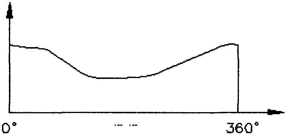
For example, a mechanical structure often used on CNC machine tools—the cam mechanism, due to the irregular nature of the cam mechanism along the circumferential direction, the force on the motor shaft at each angular position is different when the motor moves for a circle, which is not easy to simulate and debug

Method used


Image

  • Dynamic load simulation testing instrument and simulation testing method
  • Dynamic load simulation testing instrument and simulation testing method
  • Dynamic load simulation testing instrument and simulation testing method

Examples


Embodiment Construction

[0026] A dynamic load simulation tester and a simulation test method proposed by the present invention will be further described below in conjunction with the accompanying drawings and the preferred embodiment - simulated debugging cam structure.

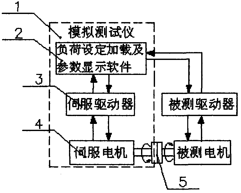
[0027] figure 1 It is a working principle diagram of a dynamic load simulation tester of the present invention. The simulation tester 1 includes a servo motor 4 , a servo driver 3 with torque drive mode, and software 2 for load setting and loading and parameter display. Among them, the servo drive 3 is connected to the host PC in a bus mode, and the load setting loading and parameter display software 2 can send control commands simulating the position-torque relationship of the actual mechanical structure to the servo drive 3 to control the movement of the servo motor 4 through the bus. Display the position, speed, torque and other actual motion information of the motor under test, and display the deviation between the control comma...


PUM


Abstract

The invention relates to a dynamic load simulation testing instrument and a simulation testing method. The dynamic simulation testing instrument comprises a servo motor, a servo driver with a moment driving mode and load setting and loading and parameter display software, wherein the load setting and loading and parameter display software can send a control command which simulates the position-moment relation of an actual mechanical structure to the servo driver through a bus for controlling the motion of the servo motor, and the servo motor is in reverse connection with a tested motor through a coupler. The simulation testing method comprises the following steps: controlling the operation of the simulation testing motor and the tested motor through the load setting and loading and parameter display software, using a PC (personal computer) to control the simulation testing motor driver to apply a moment which is reverse to that of the tested motor on the simulation testing motor by adopting the moment control mode through the load setting and loading and parameter display software, and further performing simulation testing on the tested motor. The simulation testing instrument and the simulation testing method have the advantages that the instrument has simple structure, and is convenient to operate and maintain; and the dynamic loads of various different mechanical structures, such as a cam and the like, can be simulated.

Description

technical field [0001] The invention relates to a dynamic load simulation tester and a simulation test method, which are mainly used in occasions requiring simulation and testing of parameters such as drivers and motors in the field of industrial automation, especially suitable for occasions requiring simulation and testing of dynamic loads. Background technique [0002] Motors and drives widely used in industrial production, automation and other fields usually require performance testing before leaving the factory, and parameter adjustment is required in field applications. [0003] The commonly used test method today is: the driver controls the motor movement, and at the same time, the dynamometer is connected to the motor through a coupling, a reverse torque is added to the motor, and the parameters of the motor and the driver are tested by observing the data displayed on the dynamometer system. [0004] It is also possible to simulate the on-site application of the motor...

Claims


Application Information

Patent Timeline
Patent Type & Authority Applications(China)
IPC IPC(8): G01R31/34
Inventor 郭洋符艳君曾逸
Owner ADTECH SHENZHEN TECH
Learn More