
Nail cabin assembly of linear cutting anastomat and anastomat applying nail cabin assembly

A linear cutting and stapler technology, which is applied in the field of staplers and linear cutting stapler staple cartridge components, can solve problems affecting surgical operations, cutter blade curling, and cutter exposure, etc., to ensure cutting quality, simple overall structure, Avoid the effect of the blade

Active Publication Date: 2013-05-29
B J ZH F PANTHER MEDICAL EQUIP
View PDF5 Cites 1 Cited by
  • Summary
  • Abstract
  • Description
  • Claims
  • Application Information

AI Technical Summary

Problems solved by technology

According to the difference in the structure of the cutting knife part, the existing linear cutting stapler can be divided into two types: one is that the cutting knife is connected with the belt blade of the advancing mechanism, because the cutting knife is not disposable in this structure, and The cutting knife is exposed, so defects such as cutting knife curling and impact gaps may occur during repeated use, resulting in a decrease in cutting quality and affecting surgical operations; the other is to rely on springs and a protective shell with knife grooves to achieve The protection of the cutting knife, this kind of stapler has a complex structure, consumes more materials, and the reliability of the structure is relatively low. At the same time, it has strict requirements on processing conditions.
[0003] It can be seen that the above-mentioned existing linear cutting stapler obviously still has inconvenience and defects in structure and use, and needs to be further improved urgently.

Method used


Image

  • Nail cabin assembly of linear cutting anastomat and anastomat applying nail cabin assembly
  • Nail cabin assembly of linear cutting anastomat and anastomat applying nail cabin assembly
  • Nail cabin assembly of linear cutting anastomat and anastomat applying nail cabin assembly

Examples


Embodiment Construction

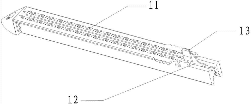
[0024] see Figure 1-4 As shown, a linear cutting stapler staple cartridge assembly 1 of the present invention includes a staple cartridge 11, a cutting knife 12, a cutting knife protective cap 13, and a knife guard shrapnel 14, and the cutting knife 12 is installed in the guide groove at the tail of the knife groove of the nail cartridge 11. Among them, the cutting knife protective cap 13 is fixed on the tail of the staple bin 11 above the cutting knife 12, and the shrapnel shrapnel 14 is fixed on the side of the cutting knife 12 inside the tail of the nail bin 11 and elastically clamped.

[0025] Wherein, as shown in the figure, the knife guard shrapnel 14 is preferably two pieces, which are in an outwardly curved arc shape, and are arranged symmetrically on both sides of the cutting knife 12 . And small-sized vertical grooves 121 can be set on both sides of the cutting knife 12, and vertical ribs 141 corresponding to the vertical grooves 121 are set on the knife guard shrap...


PUM


Abstract

The invention relates to a nail cabin assembly of a linear cutting anastomat and an anastomat applying the nail cabin assembly. The nail cabin assembly comprises a nail cabin, a cutting knife, a cutting knife protective cap and a knife protecting elastic sheet, wherein the cutting knife is mounted in a guide groove at the tail part of a nail cabin knife groove; the cutting knife protecting cap isfixed at the tail part of the nail cabin and positioned above the cutting knife; and the knife protecting elastic sheet is fixed at the tail part of the nail cabin to elastically and tightly clamp side faces of the cutting knife. The anastomat comprises an upper clamping plate, a lower clamping plate, a handle, a propelling mechanism and the nail cabin assembly; and the nail cabin assembly is mounted in the lower clamping plate. According to the invention, the nail cabin, a knife protecting frame and a spring are combined integrally to protect the cutting knife from being exposed in an non-operating state and enable the cutting knife to reciprocate in the assembly knife groove, so that a purpose of dividing human tissues, such as digestive tract is achieved and an effect of enable the anastomat to be simple in an integral structure, steady in use and convenient in operation is also achieved.

Description

technical field [0001] The invention relates to a surgical medical instrument, in particular to a staple cartridge assembly of a linear cutting stapler and a stapler using the assembly. Background technique [0002] The linear cutting stapler is a one-time use, no power supply, and only relies on mechanical force to cut human tissue. The cutting knife is a vital part of the stapler that directly affects the cutting effect and the convenience of operation. According to the difference in the structure of the cutting knife part, the existing linear cutting stapler can be divided into two types: one is that the cutting knife is connected with the belt blade of the advancing mechanism, because the cutting knife is not disposable in this structure, and The cutting knife is exposed, so defects such as cutting knife curling and impact gaps may occur during repeated use, resulting in a decrease in cutting quality and affecting surgical operations; the other is to rely on springs and ...

Claims


Application Information

Patent Timeline
Patent Type & Authority Patents(China)
IPC IPC(8): A61B17/072A61B17/3209
CPCA61B17/07207
Inventor 李学军刘青
Owner B J ZH F PANTHER MEDICAL EQUIP
Learn More