
Cross-layer interactive image quality continuous adjustable real-time video coding and decoding method

A codec method and image quality technology, applied in the field of real-time video codec, can solve problems such as lack of continuity in image quality adjustment, inability to complete resolution adjustment from D1 to HALFD1, and constraints on real-time and continuity of image quality adjustment. Achieve real-time and continuous effects

Inactive Publication Date: 2012-04-25
SOUTHEAST UNIV
View PDF2 Cites 6 Cited by
  • Summary
  • Abstract
  • Description
  • Claims
  • Application Information

AI Technical Summary

Problems solved by technology

For example, the scaling ratio supported by the progressive transmission structure of the JPEG2000 code stream can only be scaled to the power of 2 simultaneously in the length and width dimensions, such as 1 / 2, 1 / 4, etc., so the resolution from D1 to HALF D1 cannot be completed rate adjustment
[0004]Secondly, the adjustment of encoding parameters such as resolution and compression ratio in most systems needs to be reloaded to complete the firmware, so the video information during the time period of loading the firmware will be lost. Causes the interruption of video transmission and decoding, does not have the continuity of image quality adjustment
[0005] In addition, the coding parameter control of most systems requires an additional logical control channel on the basis of the code stream transmission pipeline, which is used for the transmission and confirmation of coding parameters, which restricts Real-time and continuous image quality adjustment

Method used


Image

  • Cross-layer interactive image quality continuous adjustable real-time video coding and decoding method
  • Cross-layer interactive image quality continuous adjustable real-time video coding and decoding method
  • Cross-layer interactive image quality continuous adjustable real-time video coding and decoding method

Examples


Embodiment Construction

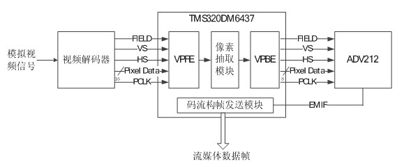
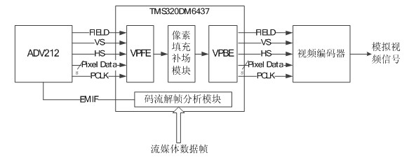
[0026] The present invention includes two parts of a video encoding end and a video decoding end, and the encoding steps of the video encoding end are as follows:

[0027] a. Before image compression of each field / frame, the encoding end checks whether it has received the image quality control command from the decoding end, and obtains the encoding control parameters in it. If not received, the original encoding control parameters are maintained;

[0028] b. The analog video signal is converted into a digital video stream with a resolution of D1 (720×576) through a video decoder;

[0029] c. The digital video code stream passes through the pixel extraction module to complete the adjustment of video resolution that meets the requirements of image quality control;

[0030] d. The digital video code stream after the resolution adjustment passes through the JPEG2000 encoding module to complete the compression encoding under the field frequency adjustment and compression ratio adju...


PUM


Abstract

The invention discloses a cross-layer interactive image quality continuous adjustable real-time video coding and decoding method. A system of the method concretely comprises a video coding terminal and a video decoding terminal. According to a received image quality control instruction, the coding terminal determines a coding parameter of present field / frame of image data, completes JPEG 2000 coding of a digital video signal according to an assigned parameter, forms a streaming media data frame formed by using data and a parameter after decoding, and sends the streaming media data frame to the decoding terminal. According to a coding parameter in the received streaming media data frame, the decoding terminal whether a previous image control instruction needs to be retransmitted or not, completes decoding and playing of a present parameter, sends a new image control instruction when image quality needs to be changed. By employing video image quality of the present system, a resolution,field frequency, and a compression ratio is flexible, continuous and adjustable, change of channel transmission bandwidth can be rapidly adapted at utmost, and the control instruction can be subjected to cross-layer interaction.

Description

technical field [0001] The invention belongs to the field of digital image processing and the technical field of multimedia message service, and specifically relates to a real-time video encoding and decoding method with flexible and continuously adjustable cross-layer interactive image quality. Background technique [0002] The richness and intuitiveness of the video signal make it widely used in traffic management, security and many other fields. Most of the current video codec systems are based on MPEG2, H.264, JPEG2000 and other technologies, and there are some deficiencies in specific applications as follows. [0003] First of all, the adjustable resolution of the system is mostly standard formats such as D1 and CIF. Because the dimensions of different formats in the dimension of length and width are multiples of 2, the rate of the coded stream after encoding is stepped, and there is no resolution and code. The flexibility of any continuous adjustment of the flow ra...

Claims


Application Information

Patent Timeline
IPC IPC(8): H04N7/26H04N19/164H04N19/59
Inventor 王刚陈晓曙
Owner SOUTHEAST UNIV
Learn More