
Device for measuring blood component concentration and method for measuring blood component concentration

A blood component and concentration measurement technology, which is applied in the direction of measuring devices, transmittance measurement, diagnostic recording/measurement, etc., can solve problems such as interference, inability to correctly and stably grasp the human pulsation cycle, etc., and achieve the effect of improving QOL

Active Publication Date: 2015-05-27
ASAHI KASEI MEDICAL CO LTD
View PDF10 Cites 0 Cited by
  • Summary
  • Abstract
  • Description
  • Claims
  • Application Information

AI Technical Summary

Problems solved by technology

However, in this case, it may not be possible to accurately and stably grasp the pulsation cycle of the human body due to the influence of, for example, disturbances unique to the blood purification circuit.

Method used


Image

  • Device for measuring blood component concentration and method for measuring blood component concentration
  • Device for measuring blood component concentration and method for measuring blood component concentration
  • Device for measuring blood component concentration and method for measuring blood component concentration

Examples


Embodiment 1

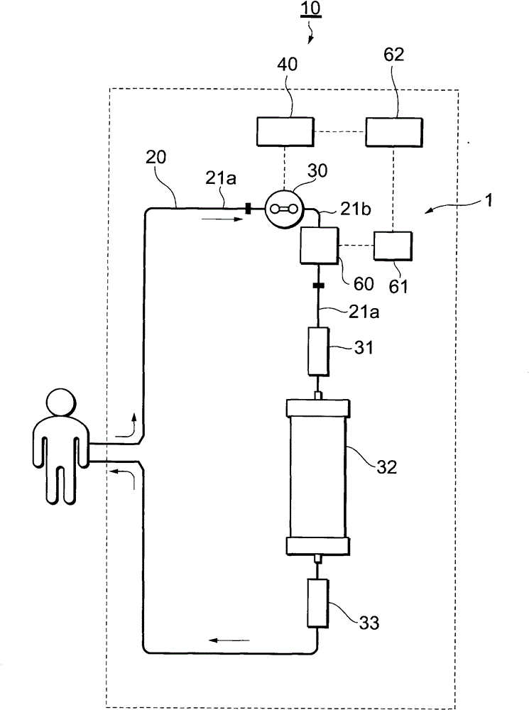
[0093] In Example 1, the following blood component concentration measuring device 1 is used: figure 1 As shown, the sensor unit 60 is provided on the downstream side of the blood pump 30 (between the blood pump 30 and the arterial side dripper 31), as shown in FIG. Figure 6 The flow path 21c of the sensor unit 60 is formed in a pillow shape as shown. Specifically, a masimo SET Radical (radical) pulse oximeter, which is a reflective sensor, is used as the sensor part 60, and the red light and The wavelengths of infrared light are 660 nm and 905 nm, respectively.

[0094] As the pillow-shaped flow path 21c, a negative pressure detecting portion (length 15.6 mm, width 36.7 mm, height 15.9 mm, hardness 52 (Shore A hardness)) of a blood circuit for dialysis (JIS T 3248) was used. A flat plate with a length of 40 mm, a width of 78 mm, and a thickness of 10 mm is used for the flat plate portion 100 on the light emitting portion 70 and the light receiving portion 71 side of the fi...

Embodiment 2

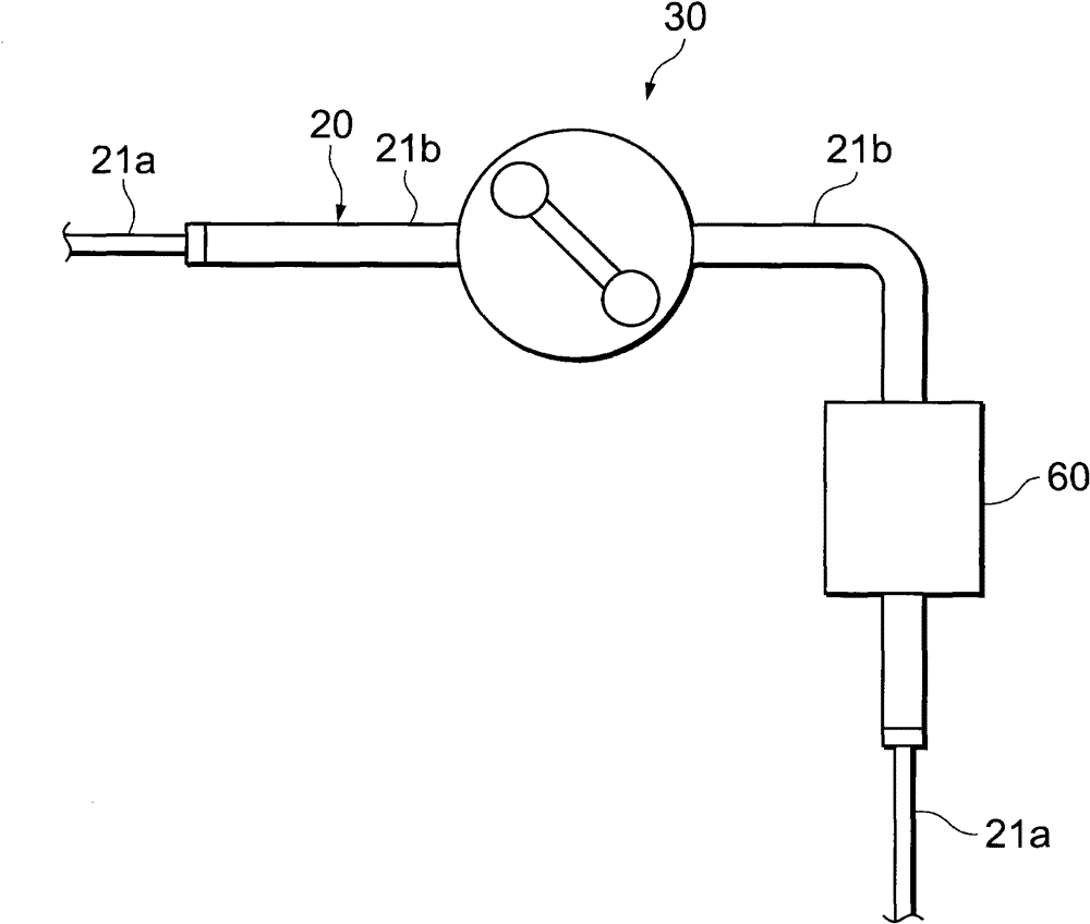
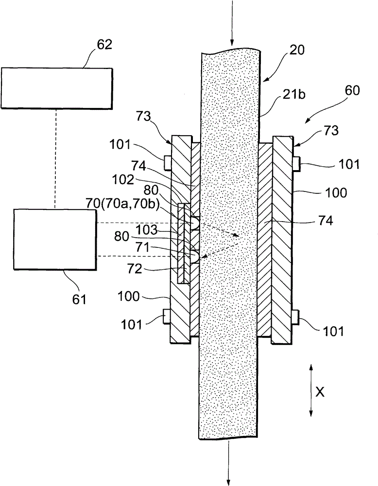
[0100] In Example 2, the following blood component concentration measuring device 1 is used: the sensor unit 60 such as figure 1 As shown, it is installed on the downstream side of the blood pump 30 (between the blood pump 30 and the arterial side drip unit 31), as image 3 as well as Figure 4 As shown, a sensor unit 60 is provided in a flow path 21 b serving as a pump tube of the blood pump 30 . Specifically, masimo SET Radical pulse oximeter, which is a reflective sensor, is used as the sensor part 60, and the wavelength of red light and infrared light of the light emitting part 70 for measuring the absorbance ratio of oxyhemoglobin and reduced hemoglobin in Radical Use 660nm and 905nm respectively.

[0101] As the flow path 21b of the blood pump 30, a blood pump tube portion (inner diameter 8.0 mm, outer diameter 12.0 mm, length 325 mm, hardness 45 (Shore A hardness)) of a blood circuit for dialysis (JIS T 3248) was used. ). A flat plate with a length of 40 mm, a widt...


PUM

PropertyMeasurementUnit
wavelengthaaaaaaaaaa
lengthaaaaaaaaaa
lengthaaaaaaaaaa

Abstract

PROBLEM TO BE SOLVED: To provide a blood component concentration measuring device capable of correctly and stably measuring the concentration of blood components in a blood purification circuit. SOLUTION: The blood component concentration measuring device 1 has: a sensor 60 having a light-emitting unit for making a light incident on blood in the blood purification circuit 20 and a light-receiving unit for detecting a light having transmitted through the blood in the blood purification circuit 20; and a calculator 72 for extracting a frequency component of the frequency F equal to the pulse of the blood generated in the blood purification circuit 20 by driving a blood pump 30 on the basis of variation in time of optical strength detected by the light-receiving unit and calculating oxygen concentration on the basis of the frequency component. The sensor 60 is provided on the blood purification circuit 20 so as to be positioned downstream of the blood pump 30.

Description

technical field [0001] The present invention relates to a blood component concentration measuring device and a blood component concentration measuring method for measuring the concentration of blood components such as oxygen saturation in blood in blood purification therapy and the like. Background technique [0002] Blood purification therapy is a therapy that uses membranes and adsorbents to remove harmful substances and useless substances in the blood exported from the body and returns the blood to the body. There are types of hemodialysis, hemofiltration dialysis, hemofiltration, and blood adsorption. [0003] For example, management of patients in hemodialysis therapy is performed by observing both changes in blood and systemic symptoms. For example, the blood pressure of a patient undergoing dialysis is lowered mainly because the circulating blood flow decreases due to dehydration. Therefore, dialysis treatment is performed while monitoring the patient's blood volume u...

Claims


Application Information

Patent Timeline
Patent Type & Authority Patents(China)
IPC IPC(8): G01N21/59A61M1/00A61B5/1455A61M1/14G01N21/35G01N21/3577G01N21/359
CPCG01N21/31G01N21/3151G01N21/3577G01N21/359G01N21/85G01N2021/3144G01N2021/3155G01N2021/3181G01N2201/064
Inventor 佐佐木正富今井胜
Owner ASAHI KASEI MEDICAL CO LTD
Learn More