
Energy converter

A technology of energy converters and barriers, applied in the direction of machines/engines, mechanical equipment, mechanisms that generate mechanical power, etc., can solve the problem of converting into mechanical energy

Active Publication Date: 2012-04-25
淮安市东方环保产业有限公司
View PDF5 Cites 0 Cited by
  • Summary
  • Abstract
  • Description
  • Claims
  • Application Information

AI Technical Summary

Problems solved by technology

[0002] As we all know, there are many types of existing power machines, such as internal combustion engines, gasoline engines, steam engines and electric motors, etc., but none of these power machines can convert a kind of energy into mechanical energy, so we have invented a new energy converter that can convert a kind of energy into mechanical energy. Convert energy into mechanical energy to achieve the purpose of doing work

Method used


Image

  • Energy converter
  • Energy converter
  • Energy converter

Examples


Embodiment Construction

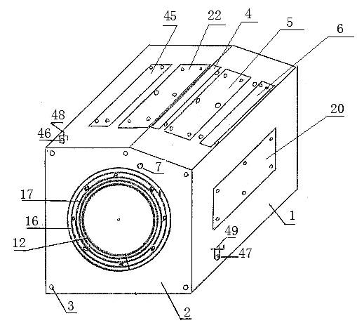
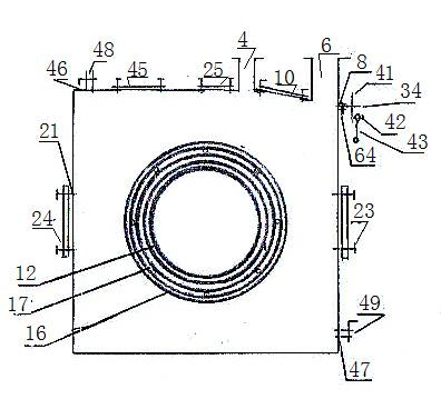
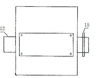
[0040] Such as Figure 1-13 As shown, the energy converter is provided with a housing 1, a housing cover 2 is provided at one end of the housing 1, and a plurality of screw mounting holes are provided at the junction of the housing cover 2 and the housing 1, and the housing cover 2 is installed with screws 3. On the shell 1, a shell cavity is formed. A sealing ring is installed at the junction of the shell cover 2 and the shell 1. A hollow shaft perforation is provided in the center of the shell cover 2 and the center of the other end of the shell 1. The hollow shaft perforates the wall A large bearing installation groove 16 is provided on the outer hole wall of the center, a large bearing 17 is installed in the large bearing installation groove 16, a hollow shaft 12 is installed on the inner hole of the large bearing 17, and the center of the upper shell vertically upwards from the center of the shell cavity is slightly offset The shell on the right is provided with an upper ...


PUM


Abstract

The invention discloses an energy converter. The energy converter is characterized in that an inner hole of a large bearing (17) of a shell is provided with a hollow shaft (12) and an upper part piston barrel (25) arranged through a mounting hole (22) of the upper part piston barrel; the right shell of the mounting hole (22) of the upper part piston barrel is provided with a waste discharge port (4), a waste discharge pipe (65) is arranged on the waste discharge port (4), and the right shell of the waste discharge port (4) is provided with a separator (10); the right shell of a mounting hole (5) of the separator is provided with an energy inlet (6), and the energy inlet (6) is provided with an energy inlet pipe (66); the right shell of the shell is provided with a right side piston barrel(23), the left shell of the shell is provided with a left side piston barrel (24), and a blocking thruster (9) is arranged on the shell below the waste discharge port (4); and the right shell of the energy inlet (6) is provided with a pushing rotation device (11), the hollow shaft (12) is provided with a piston piece shaft (14), and a piston piece (13) is arranged on the piston piece shaft (14). The energy converter provided by the invention has the advantages that chemical energy is converted into mechanical energy so as to realize do work, the structure is simple, and the maintenance is convenient.

Description

technical field [0001] The invention belongs to the field of power machines, and in particular relates to an energy converter. technical background [0002] As we all know, there are many types of existing power machines, such as internal combustion engines, gasoline engines, steam engines and electric motors, etc., but none of these power machines can convert a kind of energy into mechanical energy, so we have invented a new energy converter that can convert a kind of energy into mechanical energy. This kind of energy is converted into mechanical energy to achieve the purpose of doing work. Contents of the invention [0003] The object of the present invention is to provide an energy converter, which can convert a chemical energy into mechanical energy to perform work. The converter has a simple structure and is easy to maintain. [0004] The technical solution of the present invention is: the energy converter is provided with a casing, a casing cover is provided at one ...

Claims


Application Information

Patent Timeline
IPC IPC(8): F03G7/00
Inventor 朱崇胜
Owner 淮安市东方环保产业有限公司
Learn More