Reinforced combined arch ring for arch bridge

A reinforced, arch ring technology, applied in the direction of bridge reinforcement, arch bridges, bridges, etc., can solve the problems of difficulty in pre-stress loading operation, difficulty in pre-stressing, and inconvenience, and improve the distribution of constant load internal force, transportation and installation. Quick and easy-to-build effects

Inactive Publication Date: 2012-04-25
CHONGQING JIAOTONG UNIVERSITY
View PDF6 Cites 14 Cited by
  • Summary
  • Abstract
  • Description
  • Claims
  • Application Information

AI Technical Summary

Problems solved by technology

[0003] 1. In the "prestressed steel arch supporting reinforcement method", the distribution of the actual contact and detachment of the interface between the original main arch ring and the steel arch ring is very complicated, which is quite different from the ideal smooth and close contact state. When the axial precompression stress is applied to the arch foot of the steel arch ring, the size and distribution of the actual normal precompression stress on the contact interface between the original main arch ring and the steel arch ring are difficult to accurately estimate, and the internal force state of the original main arch ring is affected by the normal force on the interface. Because of the direct influence of the size and distribution of the precompressive stress, it is difficult to quantitatively analyze the effect of this method to strengthen the original main arch ring.
[0004] 2. In the "precompressed stress steel arch supporting reinforcement method", the steel arch ring needs to be in contact with the original main arch ring in the full length range, so the normal precompressive stress will also be distributed in the full length range of the bottom surface of the original main arch ring, In fact, according to the mechanical characteristics of the main arch ring of the arch bridge, the dead-load bending moment of each section of the original main arch ring may be positive or negative under the dead load of the existing bridge. The stress may be beneficial to the adjustment of the internal force of some sections, and may be unfavorable to the adjustment of the internal force of other sections, resulting in the inability to determine the stress distribution, or even have a negative effect
[0005] 3. In the "arch bridge precompression stress structure", the old arch rib and the new arch rib are connected through multi-point precompression stress loaders to form a high-order super-statically indeterminate structure, which makes the calculation of a reasonable pre-stress in the reinforcement design It is relatively difficult, and it also makes it difficult to estimate the mutual coupling effect between the precompression stress loaders when applying the precompression stress through the precompression stress loader, and it is difficult to accurately control the precompression stress application process. In the end, it may not be possible to achieve a reasonable old arch rib and Prestress distribution of new arch ribs
[0006] 4. In the "arch bridge precompression stress structure", it is necessary to install precompression stress loaders in multiple parts except the arch foot, which brings great difficulty and inconvenience to the precompression stress loading operation
[0007] 5. The above-mentioned technology needs to adopt an overall curved steel arch ring or a new arch rib that is compatible with the bottom line shape of the original main arch ring (arch rib).

Method used


Image

  • Reinforced combined arch ring for arch bridge
  • Reinforced combined arch ring for arch bridge
  • Reinforced combined arch ring for arch bridge

Examples


Embodiment Construction

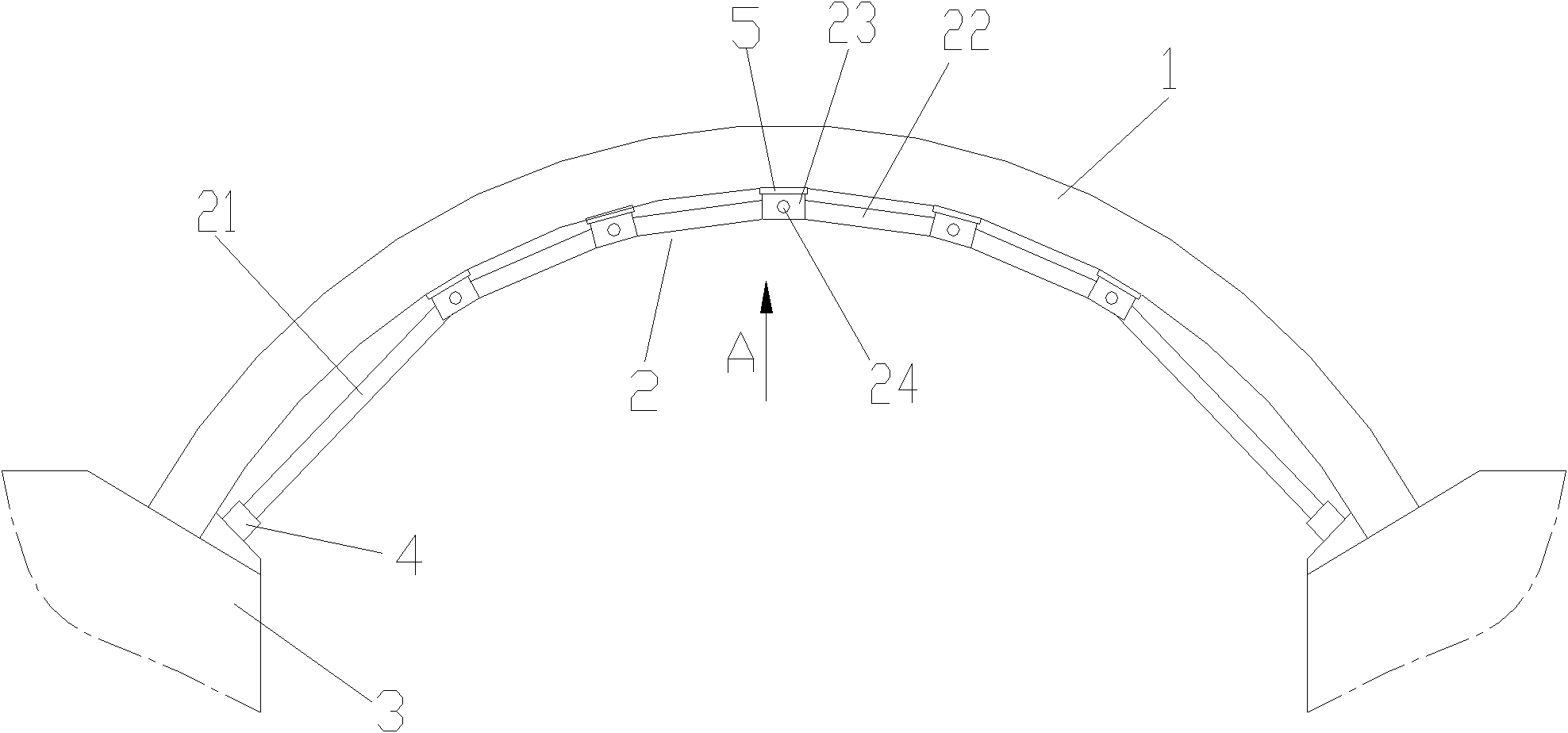
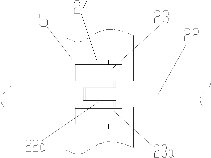
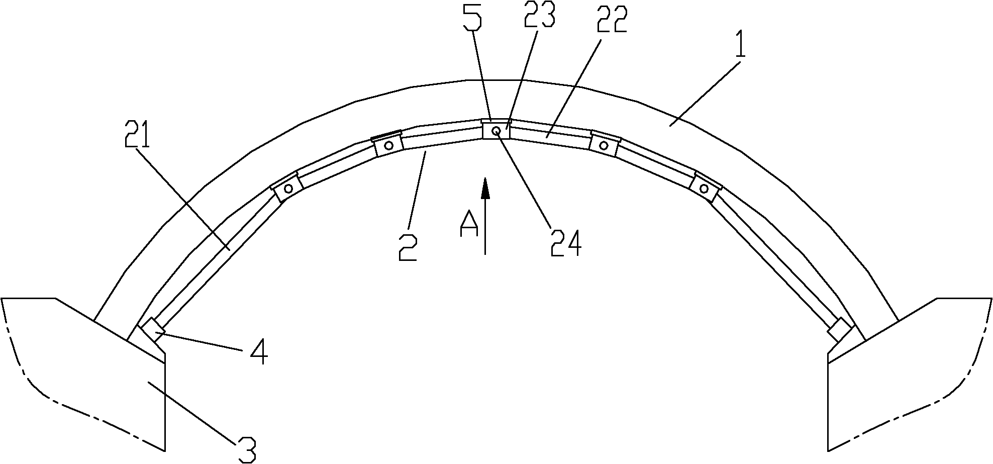
[0021] figure 1 It is a schematic diagram of the structure of the present invention, figure 2 for figure 1 View along the direction A, as shown in the figure: the arch bridge reinforced composite arch ring of this embodiment includes a main arch ring 1 and a broken-line hinged arch 2 located at the lower part of the main arch ring 1, and the broken-line hinged arch 2 is sequentially hinged. The load-bearing rods of adjacent hinges (including the load-bearing rods 22 in the middle of the broken-line hinged arch and the load-bearing rods 21 positioned at the two ends of the broken-line hinged arch) are hinged to a load-bearing member 23, such as As shown in the figure, the broken-line hinged arch 2 is formed by hinged end-to-end load-bearing rods; wherein the load-bearing rods 21 located at both ends of the broken-line hinged arch are applied with precompressive stress. The stress is transmitted sequentially and runs through the entire hinged arch; the load-bearing member 23 ...


PUM


Abstract

The invention discloses a reinforced combined arch ring for a arch bridge, comprising a main arch ring and a mansard hinge arch positioned at the lower part of the main arch ring, wherein adjacent hinged load-carrying rods are hinged to a load-carrying piece; compressive prestress is applied to the load-carrying rods at two ends of the mansard hinge arch; the load-carrying pieces are distributed at the lower part of the main arch ring, tightly propped against the lower surface of the load-carrying positive bending moment part of the main arch ring, and naturally separated with one another. The reinforced combined arch ring for the arch bridge is simple in structure, and convenient to install and transport; force magnitude and direction of prestressing applied to the main arch ring by each load-carrying piece at the hinge point are specific and can be flexibly adjusted according to requirements; the original constant load internal force distribution of the original main arch ring can be effectively modified without adding the load of the original structure; the special requirement on inner force adjustment at different sections of the main arch ring can be adapted well; and the components of the compressive prestress mansard hinge arch are detectable, maintainable and replaceable when in use, therefore, technical convenience is provided for maintenance management in the usage period of the arch ridge, the durability of the arch bridge can be effectively improved, and the service life of the arch bridge can be prolonged.

Description

technical field [0001] The invention relates to a main body structure of an arch bridge, in particular to an arch ring structure for supporting an arch bridge. Background technique [0002] An arch bridge refers to a bridge with an arch ring as the main load-bearing member of the superstructure in the vertical plane. As the main load-bearing part of the bridge, the arch ring has complex stress characteristics, and it will age after long-term use, or the design standard cannot adapt to the current load and cannot meet the long-term use standard, so the arch ring needs to be reinforced . In the arch bridge reinforcement and reconstruction project, the methods to improve the mechanical performance of the main arch ring (arch rib) mainly include several basic methods such as enlarging the section of the main arch ring, strengthening the arch rib, strengthening the transverse connection of the arch rib, and reducing the weight of the building on the arch. its combined. In the ...

Claims


Application Information

Patent Timeline
IPC IPC(8): E01D19/00E01D4/00E01D22/00
Inventor 彭凯程浩魏文财徐基平
Owner CHONGQING JIAOTONG UNIVERSITY
Why Eureka
Try Eureka