a filling machine

A filling machine and frame technology, applied in packaging, bottle filling, liquid bottling, etc., can solve problems such as complex structure of transmission components, influence on drug safety, and pollution of drug liquid, so as to simplify the mechanical structure and reduce sanitary dead ends , the effect of easy operation

Active Publication Date: 2014-10-22
TRUKING TECH LTD
View PDF3 Cites 9 Cited by
  • Summary
  • Abstract
  • Description
  • Claims
  • Application Information

AI Technical Summary

Problems solved by technology

In this structure, when the transmission assembly that makes the needle filling rack move horizontally or up and down is installed, its position is roughly around the bottle mouth of the glass bottle or even above the bottle mouth of the glass bottle, and the filling transmission mechanism is easy to move when moving. Particles are produced due to friction, and these particles will enter the glass bottle under the action of laminar wind, causing pollution to the liquid medicine in the glass bottle and directly affecting the safety of the medicine.
At the same time, since the movement of the screw rod and the synchronous belt requires a guiding structure to guide the movement, the entire transmission assembly has a complex structure, many parts, and the structure is not easy to clean due to the use of lubricating oil, resulting in sanitary dead ends

Method used


Image

  • a filling machine
  • a filling machine
  • a filling machine

Examples


Embodiment Construction

[0025] The present invention will be further described in detail below in conjunction with the accompanying drawings and specific embodiments.

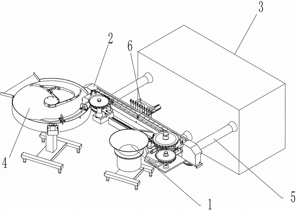
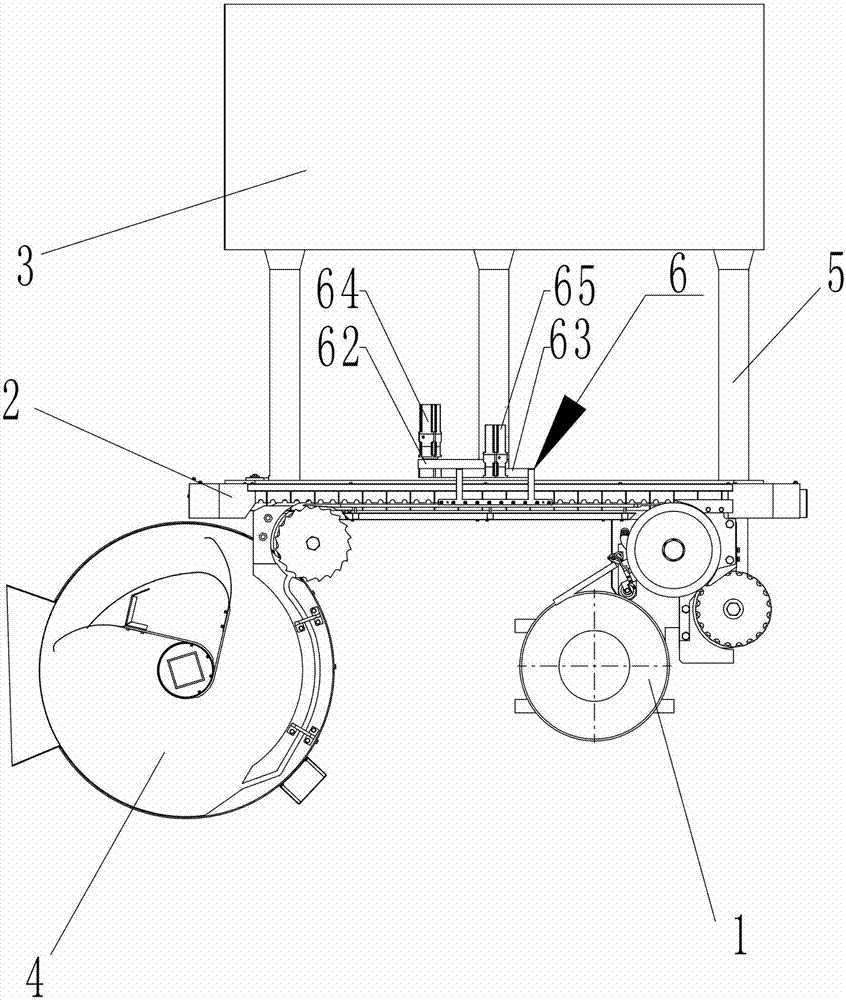
[0026] Such as figure 2 and image 3 As shown, the filling machine of the present invention includes a bottle inlet assembly 1, a bottle delivery assembly 2, a frame assembly 3, a filling assembly 6 and a bottle outlet assembly 4, and a bottle inlet assembly 1, a bottle outlet assembly 4 and a frame assembly 3 They are respectively installed on the ground through their respective supporting components. The bottle inlet assembly 1 is used to transfer the glass bottles of the previous process to the bottle delivery assembly 2. The filling assembly 6 is used to complete the filling operation of the glass bottles. The bottle output assembly 4 It is used to convey the filled glass bottles to the next process. In this embodiment, the bottle conveying assembly 2 is mainly composed of a conveyor belt, which is used to convey the glass bott...


PUM


Abstract

The invention discloses a filling machine, which comprises a bottle inlet component, a bottle conveying component, a frame component, a filling component and a bottle outlet component, wherein the bottle inlet component, the bottle outlet component and the frame component are arranged on the ground through respective support parts; the bottle conveying component and the frame component are arranged side by side, and a distance is formed between the bottle conveying component and the frame component; and the bottle conveying component is supported and connected to the frame component through more than one support beams. The filling machine has the advantages of simple and compact structure, reasonable layout, simple operation, capacity of improving the reliability and cleanness of the whole machine and the like.

Description

technical field [0001] The invention mainly relates to the fields of packaging equipment for medicine and food, in particular to a filling machine. Background technique [0002] Such as figure 1 As shown, the existing filling machine generally includes: a bottle inlet assembly 1 , a bottle delivery assembly 2 , a frame assembly 3 , a filling assembly 6 and a bottle output assembly 4 . Wherein, the filling assembly 6 is installed on the frame platen of the frame assembly 3, and the bottle-inlet assembly 1, the bottle-out assembly 4 and the frame assembly 3 are respectively installed on the ground of the working area of ​​the filling machine through respective support components, The bottle transport assembly 2 is directly installed on the side wall of the frame assembly 3, the transmission part of the bottle transport assembly 2 is installed in the frame assembly 3, and the working part of the bottle transport assembly 2 is close to the frame platen on the frame assembly 3, ...

Claims


Application Information

Patent Timeline
Patent Type & Authority Patents(China)
IPC IPC(8): B67C3/02B67C3/22B67C3/26
Inventor 陈衡山周飞跃唐岳
Owner TRUKING TECH LTD
Why Eureka
Try Eureka