
Woven filter fabric for a band filter

A belt filter, filter technology, applied in membrane filters, fabrics, filtration and separation, etc., can solve the problem that filter cloth is not suitable for vacuum belt filter and so on

Inactive Publication Date: 2012-04-18
SMS DEMAG AG
View PDF5 Cites 3 Cited by
  • Summary
  • Abstract
  • Description
  • Claims
  • Application Information

AI Technical Summary

Problems solved by technology

[0010] Known filter cloths have proven unsuitable for use in vacuum belt filters

Method used


Image

  • Woven filter fabric for a band filter
  • Woven filter fabric for a band filter
  • Woven filter fabric for a band filter

Examples


Embodiment Construction

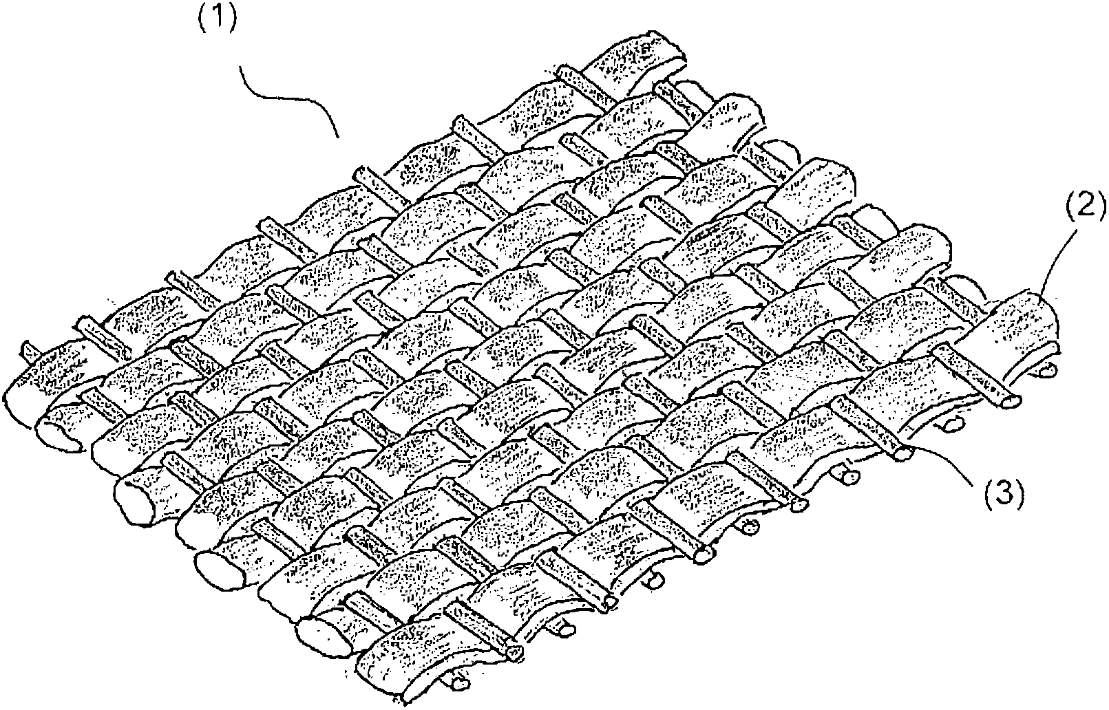
[0026] figure 1 The filter fabric 1 shown is made with a thickness of about 27 μm, with a thickness of 100 l / (min*dm 2 ), 200l / (min*dm 2 ) and 350l / (min*dm 2 ) of breathable PFA-monofilament-standard yarn (Standartfaden). Here, weft threads 2 and warp threads 3 are woven into a filter fabric 1 8000 mm long by 800 mm wide with 31 warp threads and 20 weft threads per 1 cm. After weaving, the filter fabric 1 was calendered three times to create breathability. Heat and pressure are brought into the fabric by hot and cold rolling. Here, the fabric was shrunk by about 10% to have 31 yarns per 0.7 cm, a length of 7000 mm, and a width of 700 mm.

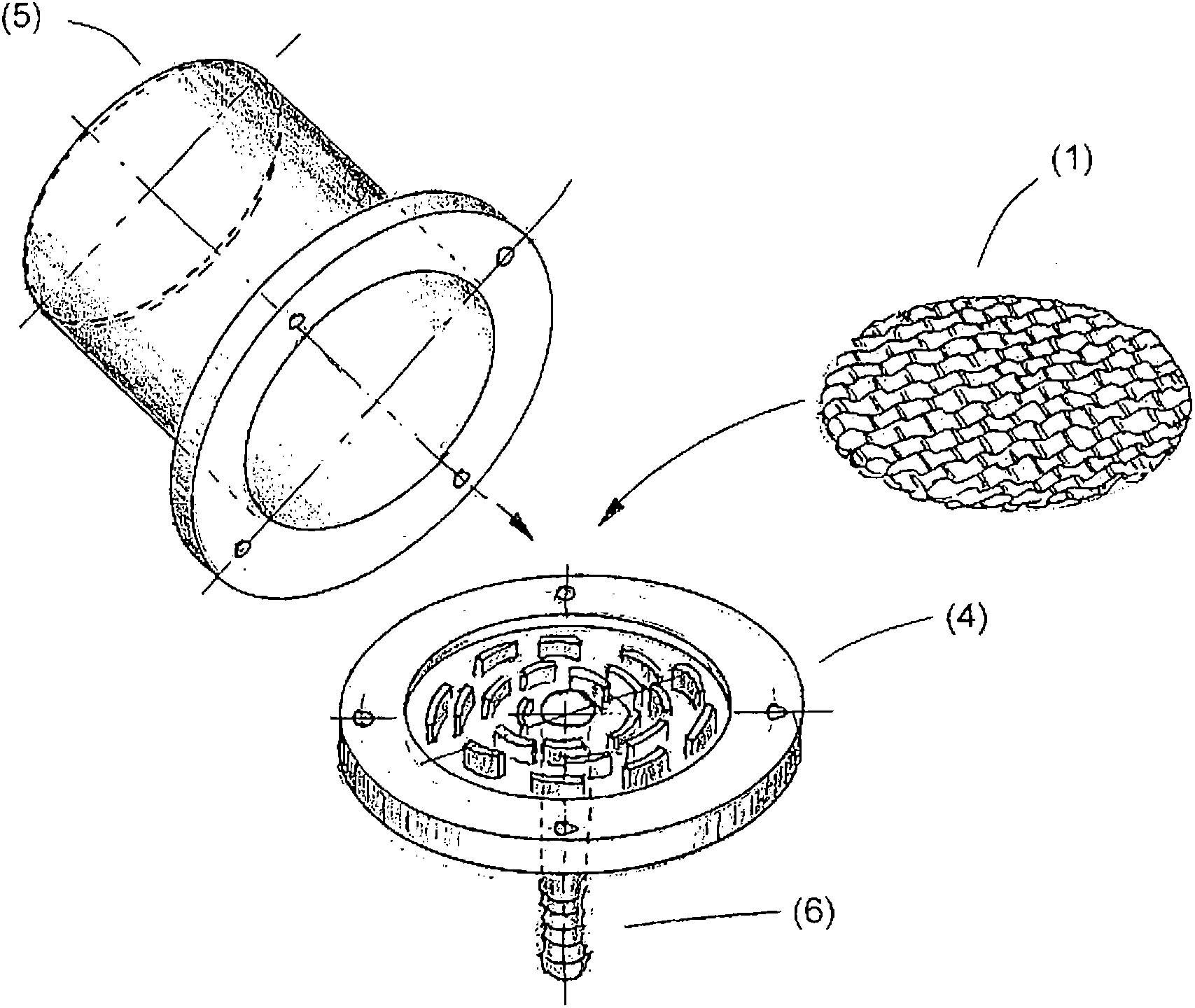
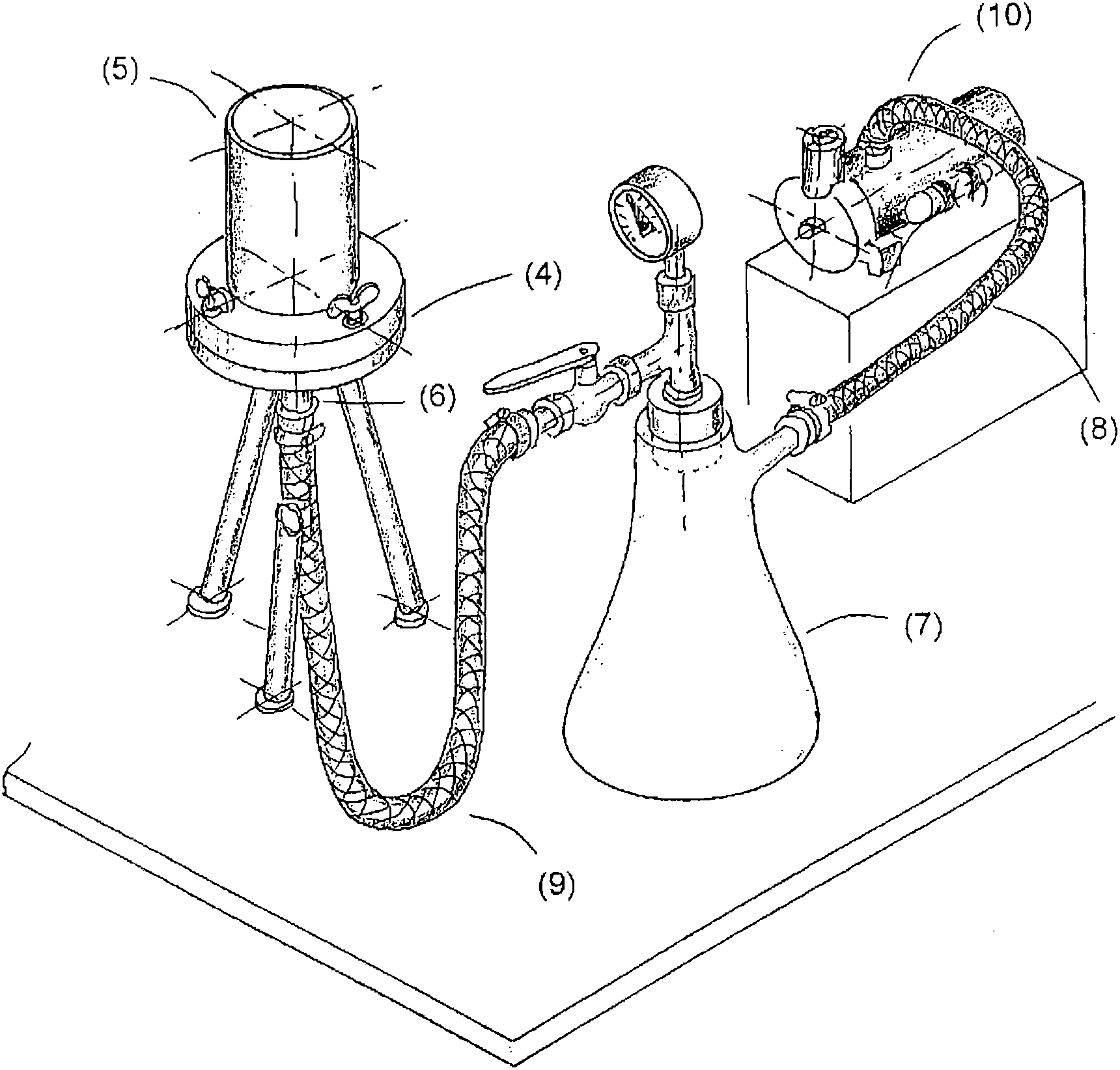
[0027] exist figure 2 The suction filter 4 with cover 5 shown in is an important part of the experimental setup for testing the filter fabric 1 . The filter fabric 1 is placed on the suction filter 4, and the suction filter 4 is screwed with the cover 5. The suction filter 4 has a suction pipe 6 in the lower region. A vacuum hose 9...


PUM

PropertyMeasurementUnit
thicknessaaaaaaaaaa
thicknessaaaaaaaaaa
particle sizeaaaaaaaaaa

Abstract

The present invention relates to a woven filter fabric for a band filter, wherein the air permeability of the woven filter fabric is 100 l / (min*dm2) to 350 l / (min*dm2) and the fibers of the woven filter fabric have a fiber thickness of 25 [mu]m to 35 [mu]m and contain from 50 wt.-% to 100 wt.-% perfluoroalkoxyl alkane (PFA). The woven filter fabric comprises 25 to 35 warp threads (3) and 15 to 25 weft threads (2) per 1 cm.

Description

technical field [0001] The invention relates to a filter fabric for a band filter, in particular for use in the acid regeneration of hydrothermal fluids. Background technique [0002] In acid regeneration of hydrothermal fluids, iron oxides, especially Fe 2 O 3 from about 75% aqueous FeCl 3 The solution precipitated at a temperature of about 170°C and was filtered off. [0003] In hydrothermal acid regeneration, for metal working, especially after acid etching of metal strips, it is involved by FeCl 2 Regeneration of contaminated hydrochloric acid. The following method steps are implemented here. [0004] (1) Contains FeCl 2 The hydrochloric acid was concentrated. [0005] (2) FeCl 2 with O 2 Oxidized to FeCl at 150°C and 7bar 3 : [0006] 2FeCl 2 +2HCl+1 / 2O 2 →2FeCl 3 +H 2 O [0007] (3) Fe 2 O 3 Precipitation in hydrolysis at 170°C and ambient pressure. To obtain reusable 18%-30% hydrochloric acid: [0008] 2FeCl 3 +3H 2 O→Fe 2 O 3 ↓+6HCl↑ [0009]...

Claims


Application Information

Patent Timeline
Patent Type & Authority Applications(China)
IPC IPC(8): B01D39/08
CPCD10B2321/042B01D2239/1291B01D39/083B01D2239/1233D10B2505/04D10B2505/00D03D13/008D03D15/00Y10T442/2164Y10T442/3065Y10T442/2139Y10T442/322D03D15/283B01D39/14B01D39/08
Inventor J·吉尔-祖克托M·巴特尔D·福格尔J·库尔曼
Owner SMS DEMAG AG
Learn More