Eureka AIR delivers breakthrough ideas for toughest innovation challenges, trusted by R&D personnel around the world.

On-pile travelling device

A walking device and supporting leg technology, applied in sheet pile wall, construction, infrastructure engineering and other directions, can solve the problems of difficulty in adapting to piling requirements, low piling efficiency, heavy piling equipment, etc., to reduce processing workload and simple structure. Reliable, easy-to-motion effects

Inactive Publication Date: 2013-10-30
HOHAI UNIV CHANGZHOU
View PDF7 Cites 0 Cited by
  • Summary
  • Abstract
  • Description
  • Claims
  • Application Information

AI Technical Summary

Problems solved by technology

[0002] In the engineering construction process of embankment rescue, swamp, shallow water and other terrain conditions, pile driving is often required. Most of the pile drivers in the traditional sense use wheel or crawler walking mechanisms, or the pile driver is placed on the ship for construction. The equipment is heavy, difficult to move during the piling process, and the piling efficiency is not high, so it is difficult to adapt to the piling requirements in complex environments such as swamps and shallow water

Method used


Image

  • On-pile travelling device
  • On-pile travelling device
  • On-pile travelling device

Examples


Embodiment 1

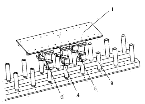
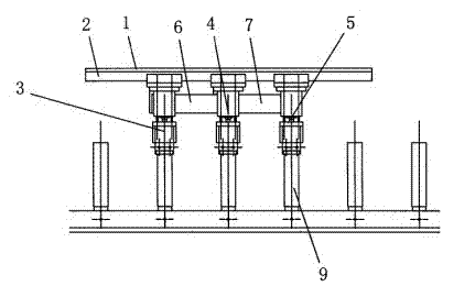
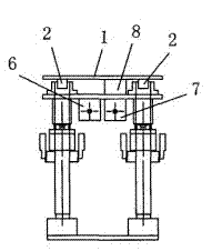
[0023] Such as Figure 1~5 As shown, a walking device on a pile includes a frame 1, a guide rail 2, a front group of support legs 3, a middle group of support legs 4, a rear group of support legs 5, a front horizontal cylinder 6, a rear horizontal cylinder 7, and a frame connecting plate 8. The support leg 4 of the middle group is fixedly connected with the frame 1 through the frame connecting plate 8, the support leg 3 of the front group is connected with the support leg 4 of the middle group through the front horizontal cylinder 6, and the support leg 4 of the middle group is connected with the rear horizontal cylinder 7 through the rear horizontal cylinder 7. The group of support legs 5 is connected, and the guide rail 2 has two left and right, and is fixed on the frame 1 respectively.

[0024] Such as image 3 , 4 As shown, the front group of support legs 3, the middle group of support legs 4 and the rear group of support legs 5 are all made up of a left leg 18, a right ...

Embodiment 2

[0027] Such as Figure 6 Shown, front additional group support leg 14 is also provided with in the front of front group support leg 3, front additional group support leg 14 links to each other with front group support leg 3 by front additional cylinder 15; Front additional group support leg 14 is formed by left supporting leg 18. The right leg 19, the leg connecting plate 20, the left slider 21 and the right slider 22 are composed, wherein the left leg 18 and the right leg 19 are respectively fixed at the two ends of the lower side of the leg connecting plate 20, and the left The slide block 21 and the right slide block 22 are respectively fixed on the two ends of the upper side of the leg connecting plate 20 , and are slidably fitted with the guide rail 2 fixed on the frame 1 .

[0028] Such as Figure 6 Shown, also be provided with rear additional group support leg 16 in the back of rear group support leg 5, rear additional group support leg 16 links to each other with rear...


PUM


Abstract

The invention relates to an on-pile travelling device. The on-pile travelling device comprises a rack (1), guide rails (2), a front group of supporting legs (3), a middle group of supporting legs (4), a back group of supporting legs (5), a front horizontal cylinder (6), a back horizontal cylinder (7) and a rack connecting plate (8), wherein the middle group of supporting legs (4) are fixedly connected with the rack (1) through the rack connecting plate (8); the front group of supporting legs (3) are connected with the middle group of supporting legs (4) through the front horizontal cylinder (6); the middle group of supporting legs (4) are connected with the back group of supporting legs (5) through the back horizontal cylinder (7); and the guide rails (2) comprise a left guide rail and a right guide rail and are respectively fixed to the rack (1). The on-pile traveling device can travel on an implanted pile body, and the moving efficiency and the piling efficiency of a piling machine are greatly improved.

Description

technical field [0001] The invention relates to a traveling device on a pile, which belongs to the field of piling in the engineering construction process. Background technique [0002] In the engineering construction process of embankment rescue, swamp, shallow water and other terrain conditions, pile driving is often required. Most of the traditional pile drivers use wheel or crawler walking mechanism, or the pile driver is placed on the ship for construction, which not only makes piling The equipment is bulky, difficult to move during the piling process, and the piling efficiency is not high, so it is difficult to adapt to the piling requirements in complex environments such as swamps and shallow water. [0003] Aiming at the special requirements of the pile driver in the complicated environment, the invention designs a walking device of the pile driver which can walk on the implanted pile body. Contents of the invention [0004] The object of the present invention is...

Claims


Application Information

Patent Timeline
Patent Type & Authority Patents(China)
IPC IPC(8): E02D7/00
Inventor 何钢居玲彭正弘蔡金杰朱灯林
Owner HOHAI UNIV CHANGZHOU
Why Eureka
Eureka Blog
Learn More